Parallel interface signals – Compuprint 10200 Programmer Manual User Manual
Page 213
Interfaces
209
P
P
a
a
r
r
a
a
l
l
l
l
e
e
l
l
I
I
n
n
t
t
e
e
r
r
f
f
a
a
c
c
e
e
S
S
i
i
g
g
n
n
a
a
l
l
s
s
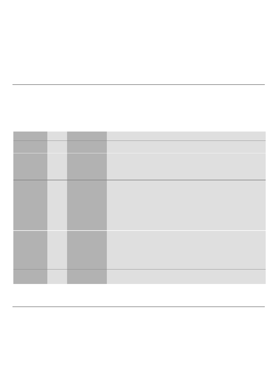
Description of the signals in monodirectional link:
Signal Name Pin N°
Source
Description
STROBE
1
HOST
Clock signal which controls data transmission with its falling edge.
ACK
10
PRINTER
Negative pulsed signal indicating that the printer has received data and
is ready to accept the next set of data. Also sent when the printer is
switched from off-line to on-line and at the end of the initialization time.
The BUSY line is always active.
DATA BIT 1
DATA BIT 2
DATA BIT 3
DATA BIT 4
DATA BIT 5
DATA BIT 6
DATA BIT 7
DATA BIT 8
2
3
4
5
6
7
8
9
PRINTER /
HOST
Data 8 is the most significant bit. These are the data lines used by host
or printer to transfer control code or ASCII codes.
BUSY
11
PRINTER
When high, this signal indicates that the printer cannot accept data
or control codes. This signal goes high during data processing, in
test and program modes, during initialization, when the buffer is full,
and when a paper jam, paper end or paper size error occurs, in
case of a power-on reset, the reception of a STROBE signal, while
the register was not yet read, or when the INIT line is still active.
PE
12
PRINTER
When high, this signal indicates that the automatic input bin is out of
paper and paper cannot be loaded from an other bin.