E.1 connector pinouts, E.2 installation instructions, E.2.1 parts required – Comtech EF Data SDM-650B User Manual
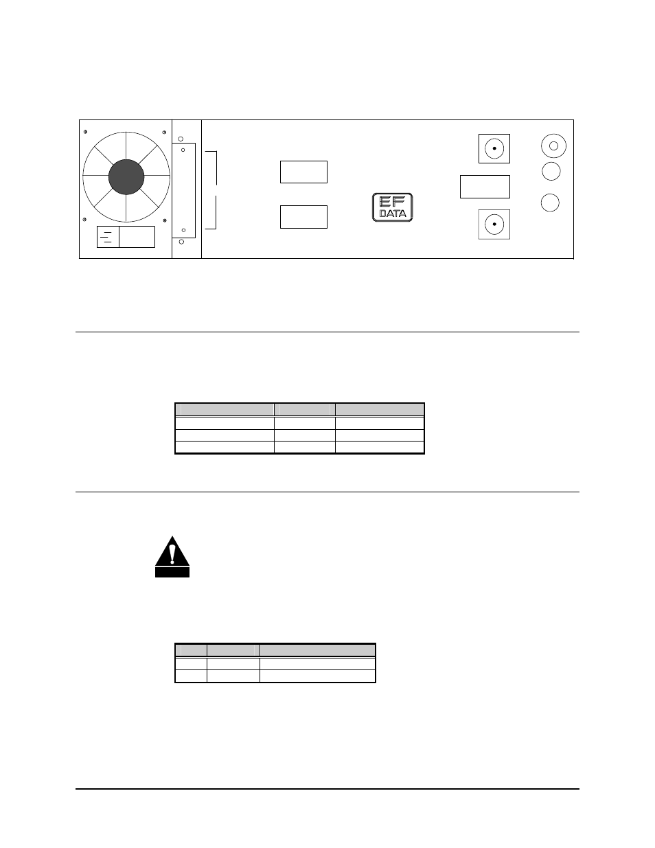
Page 254: Figure e-1. rear panel view
Advertising
AGC Interface
SDM-650B Satellite Modem
E–2
Rev.
5
GROUND
ERDE
REMOTE
FAULT
J8
DATA
I/OI
J7
J6
CP1
CP2
TX/IF
OUTPUT
RX/IF
INPUT
MADE IN USA
J9
AGC
GAIN
OFFSET
J10
J11
Figure E-1. Rear Panel View
E.1 Connector Pinouts
The AGC interface is supplied on a 9-pin female D connector that is accessible from the
rear panel. Screw locks are provided for mechanical security of the mating connector.
Function
Name
Pin #
GROUND GND
9
AGC OUTPUT
AGC-OUT
1
NO CONNECTION
NC
2, 3, 4, 5, 6, 7, 8
E.2 Installation Instructions
CAUTION
Parts and assemblies may be damaged by Electrostatic Discharge (ESD).
ESD safety precautions should always be observed when handling parts.
E.2.1 Parts Required
Qty.
Part #
Description
1 PC/0769 AGC
Interface
1
FP/1873
Back Panel for the AGC
Advertising