2 connector pinouts – Comtech EF Data SDM-650B User Manual
Page 54
Advertising
Configuration
SDM-650B Satellite Modem
3–12
Rev.
5
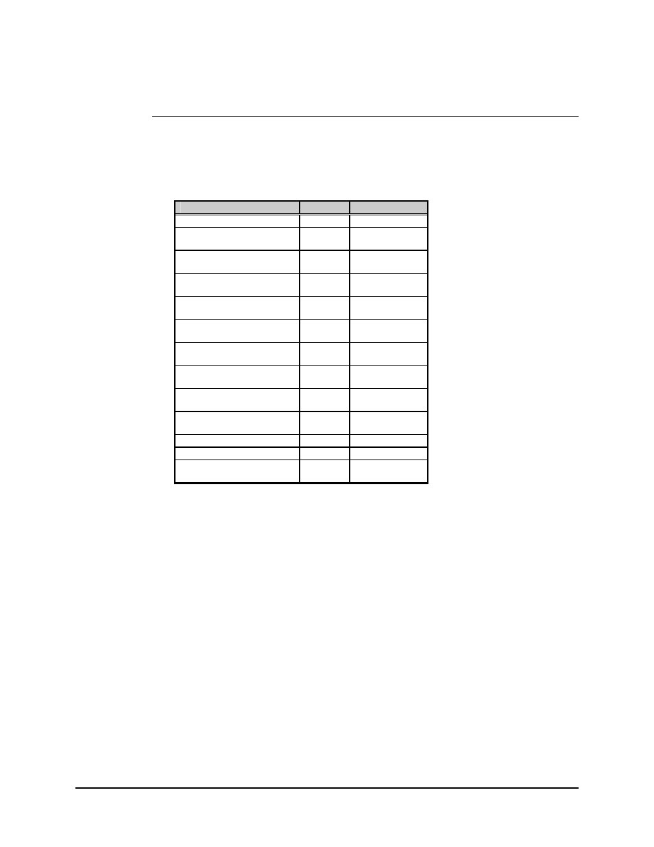
3.2.1.2 Connector Pinouts
The RS-422 and MIL-STD-188-114 interface is provided on a 37-pin female D
connector, accessible from the rear panel of the modem. Screw locks are provided for
mechanical security of the mating connector.
Signal Function
Name
Pin #
SIGNAL GROUND
SG
1, 19, 20, 37
SEND DATA
SD-A
SD-B
4
22
SEND TIMING
ST-A
ST-B
5
23
RECEIVE DATA
RD-A
RD-B
6
24
REQUEST TO SEND
RS-A
RS-B
7
25
RECEIVER TIMING
RT-A
RT-B
8
26
CLEAR TO SEND
CS-A
CS-B
9
27
DATA MODE
DM-A
DM-B
11
29
RECEIVER READY
RR-A
RR-B
13
31
TERMINAL TIMING
TT-A
TT-B
17
35
MOD FAULT
−
3
DEMOD FAULT
−
21
MASTER CLOCK
(INPUT)
MC-A
MC-B
16
34
Advertising