2 connector pinouts, 3 specification – Comtech EF Data SDM-650B User Manual
Page 65
SDM-650B Satellite Modem
Configuration
Rev. 5
3–23
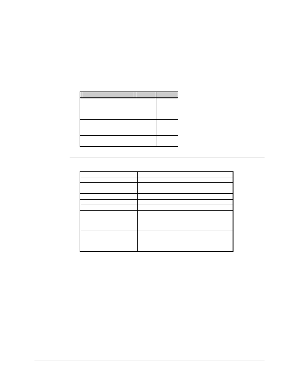
3.2.3.2 Connector Pinouts
The DS-1 interface is provided on a 15-pin female D connector accessible from the
modem rear panel. Screw locks are provided for mechanical security of the mating
connector.
Signal Function
Name
Pin #
SEND DATA
SD-A
SD-B
1
9
RECEIVE DATA
RD-A
RD-B
3
11
MASTER CLOCK
MC-A
MC-B
7
8
MODULATOR FAULT
----
14
DEMODULATOR FAULT
----
15
GROUND GND
2,
4
3.2.3.3 Specification
Circuits Supported
SD, RD, MOD FAULT, DEMOD FAULT
Data Rate
1.544 Mbit/s
±
100 bit/s
Pulse Width (RD)
324,
±
50 ns
Line Code
AMI or B8ZS (selectable)
RD Amplitude
2.75,
±
0.25V pk into a 100
Ω termination
SD Amplitude
3,
±
1.5V pk into a 100
Ω
termination
Jitter Attenuation (SD)
Meets AT&T Publication 62411 specification
Modulator Fault
Open collector output
15V max
20 mA current sink
Fault is open circuit
Demodulator Fault
Open collector output
15V max
20 mA current sink
Fault is open circuit