Comtech EF Data SDM-650B User Manual
Page 93
SDM-650B Satellite Modem
Configuration
Rev. 5
3–51
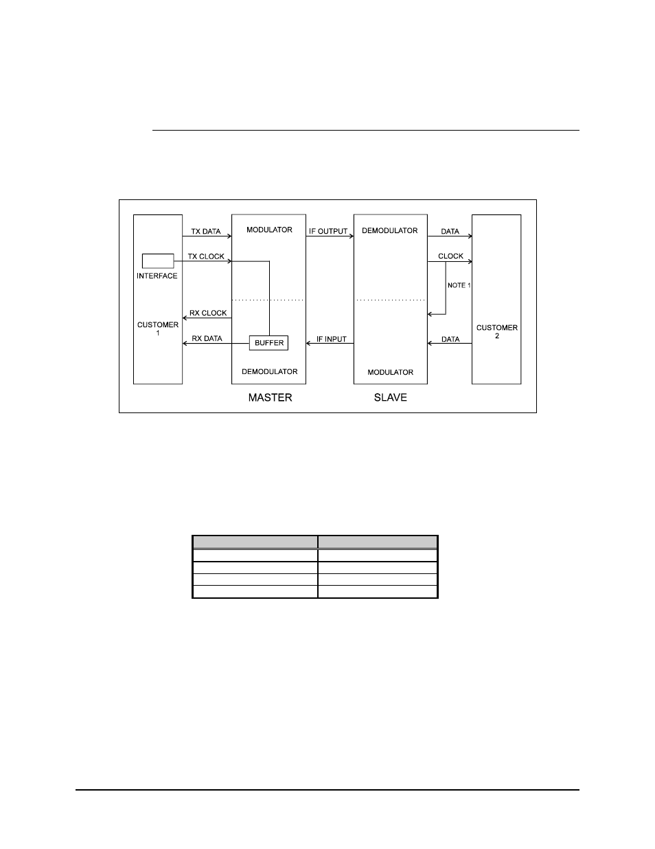
3.6.1.1 Master/Slave RS-422 or V.35
Refer to Figure 3-16 for the RS-422 or V.35 master/slave configuration.
Figure 3-16. RS-422 or V.35 Master Slave Configuration
Notes:
1. The clock may be looped back by using JP10 on the interface board.
2. Refer to Tables 3-1 or 3-2 for more information.
RS-422 Clock Loopback
V.35 Clock Loopback
Join RT-A to TT-A
Join SCR-A to SCTE-A
Join pin 8 to pin 17
Join pin V to pin U
Join RT-B to TT-B
Join SCR-B to SCTE-B
Join pin 26 to pin 35
Join pin X to pin Y
Note: By wiring the interface for clock turnaround, the impedance will be
reduced. This generally will cause no problem, providing the cable length to the
final terminal equipment is not excessive. Selecting “no loading” at the terminal
equipment will ensure correct line matching.