4 connector pinouts – Comtech EF Data SDM-650B User Manual
Page 69
Advertising
SDM-650B Satellite Modem
Configuration
Rev. 5
3–27
3.2.4.3 Switch Configuration for G.703 2048 kbit/s Interface
Switch 1 is an 8-position dip switch located at the end of the G.703 interface board.
Table 3-4 lists the switch settings for data rates and available coding for the G.703
2048 kbit/s interface.
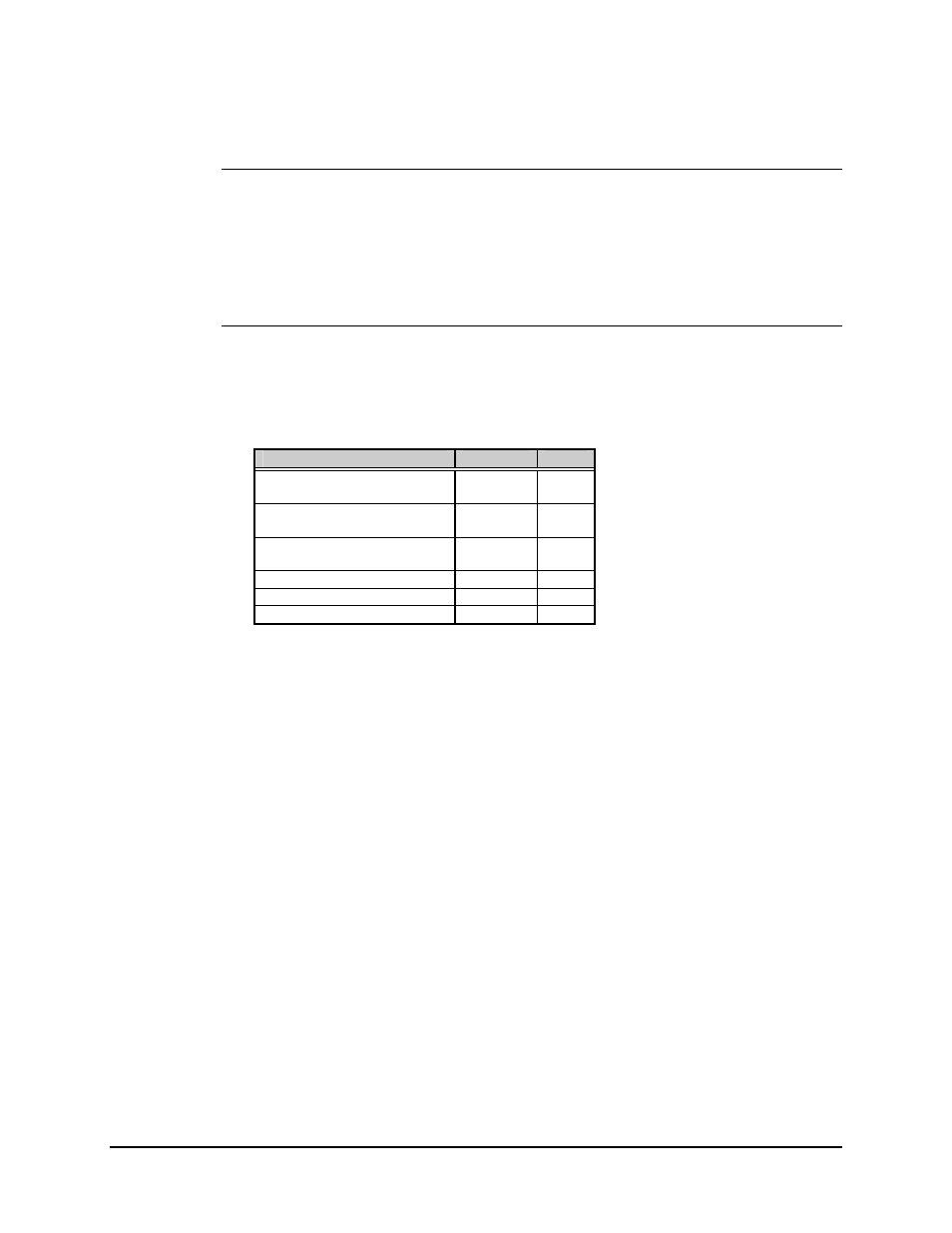
3.2.4.4 Connector Pinouts
The G.703 2048 kbit/s interface is provided on a 15-pin female D connector accessible
from the rear panel of the modem. Screw locks are provided for mechanical security of
the mating connector.
Signal Function
Name
Pin #
SEND DATA
SD-A
SD-B
1
9
RECEIVE DATA
RD-A
RD-B
3
11
MASTER CLOCK
MC-A
MC-B
7
8
MODULATOR FAULT
----
14
DEMODULATOR FAULT
----
15
GROUND GND
2,
4
Advertising