Cybex 55620H Modular User Manual
Page 73
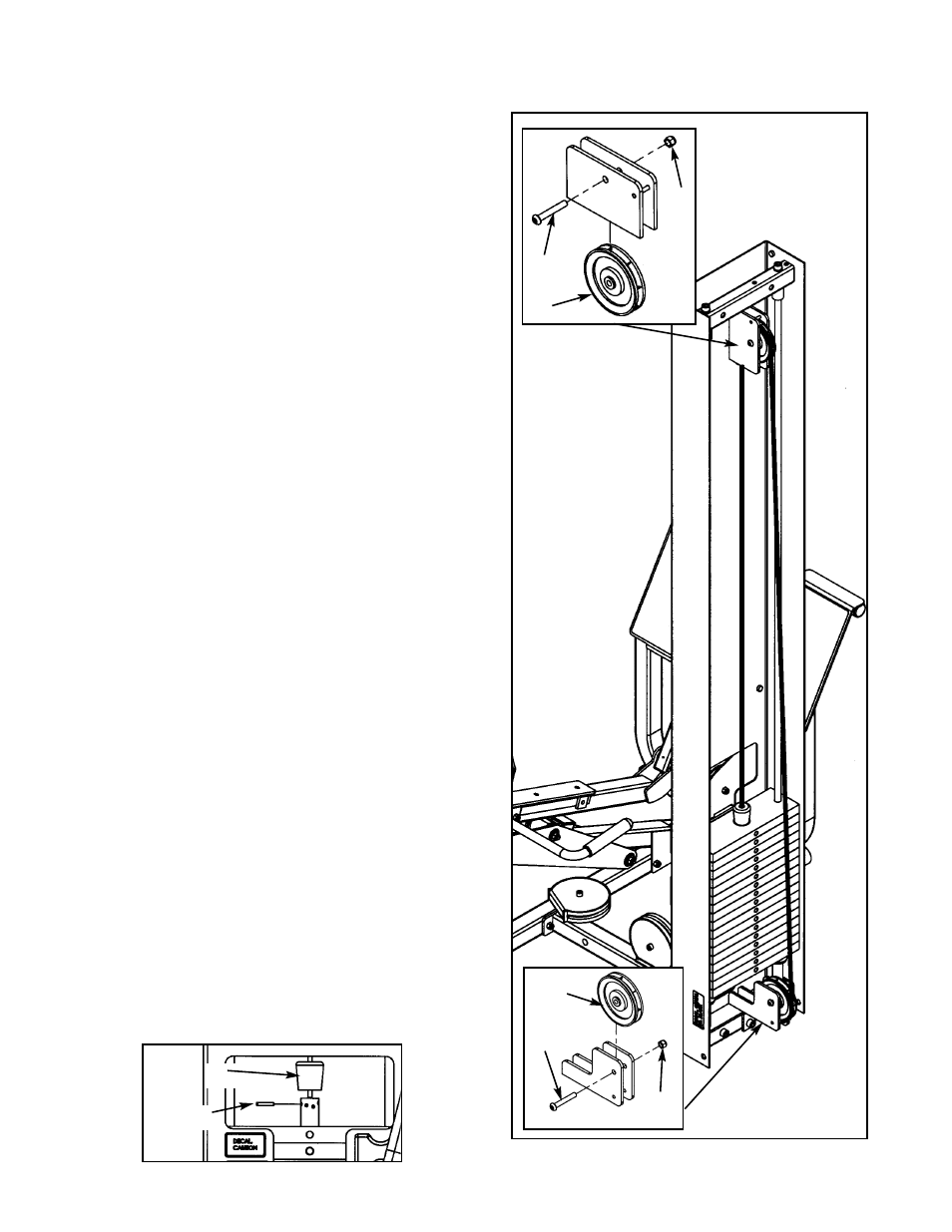
7. Routing Cable - Modular/Tandem configuration
only (see steps 7A - 7I, Figures 16 and 17).
NOTE: For Free Standing configuration see
step 8.
A. Install upper assemblies to any stations within
the Modular/Tandem configuration that
contain upper assemblies. See the Modular
and Tandem installation instructions.
B. Locate two pulleys (#1), two BHSCS .375-16 x
2.50 (#72) and two nylon locknuts .375-16
(#33).
C. At the same time, install pulley to lower pulley
bracket and route cable using one pulley (#1),
one BHSCS .375-16 x 2.50 (#72) and one
nylon locknut .375-16 (#33). See Figure 16.
D. Route cable to upper pulley bracket and
install pulley/route cable using one pulley (#1),
one BHSCS .375-16 x 2.50 (#72) and one
nylon locknut .375-16 (#33). See Figure 16.
E. Route cable downward to top plate.
F. Slide rubber boot (#12) onto cable end. See
Figures 16 and 17.
G. Insert cable end into top weight and align
cable fitting opening with opening in top
weight for proper cable tension as shown in
Figure 17. See the Owner’s Manual for proper
cable adjustment.
H. Using a hammer, drive roll pin (#8) through top
plate connector and cable fitting. Assure pin is
flush with top plate collar.
I.
Insert selector pin into each weight plate to
assure proper alignment. See the Cable
Adjustment and Installation section of the
Owner’s Manual if the selector pin does not fit
smoothly or if cable appears to have
excessive slack.
1
72
33
33
72
1
Figure 17
12
8
Cybex Modular Owner’s Manual
Page 4-19