Cybex 55620H Modular User Manual
Page 75
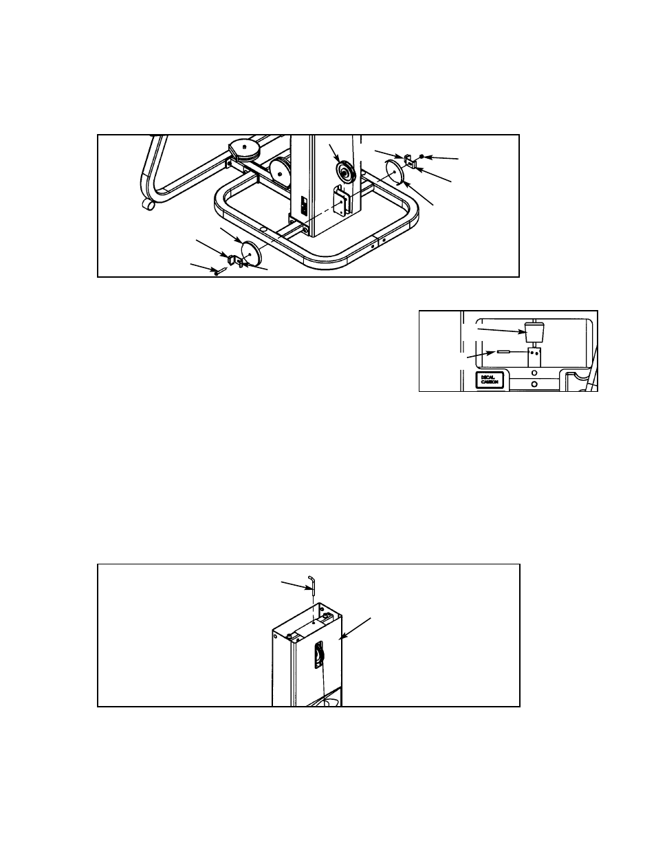
D. Install lower pulley using one pulleys (#1), one BHSCS .375-16 x 2.50 (#72), one nylon
locknut .375-16 (#33), two stop brackets (#68)/bumpers (#42) and two pulley guards (#67).
See Figure 20.
Figure 20
Figure 22
E. Route cable downward to top plate.
F. Slide rubber boot (#12) onto cable end. See Figure 21.
G. Insert cable end into top weight and align cable fitting
opening with opening in top weight for proper cable
tension as shown in Figure 21. See the Owner’s
Manual for proper cable adjustment.
H. Using a hammer, drive roll pin (#8) through top plate connector and cable fitting. Assure pin is
flush with top plate collar.
I.
Insert selector pin into each weight plate to assure proper alignment. See the Cable
Adjustment and Installation section of the Owner’s Manual if the selector pin does not fit
smoothly or if cable appears to have excessive slack.
J. Secure back cover (#66) using weight selector pin (#71). See Figure 22.
1
33
67
67
68
42
42
68
72
71
66
Figure 21
12
8
Cybex Modular Owner’s Manual
Page 4-21