Cybex 55620H Modular User Manual
Page 89
4. Attach column to the appropriate configuration (see steps 4A - 4F, Figures 8 and 9).
NOTE: For Free Standing configuration, see steps 4A - 4C then go to step 5.
For Tandem configuration see step 4D and 4E then go to step 5.
For Modular configurations see step 4D and 4F then go to step 5.
A. Place the base assembly (#65) in area where the station will be used.
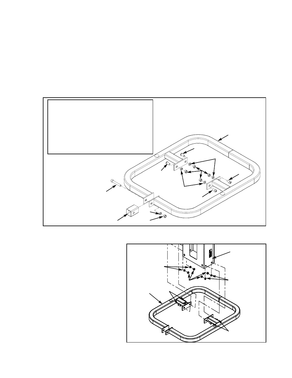
B. Remove the hardware from the base (#65A) as shown in Figure 8.
65
1
5302-51
Base Assembly
65A
1
5301-200
Base
65B
5
HN784000
Hex Nut .50-13
65C
4
JC780417
BHSCS .50-13 x 1.00
65D
1
JC782836
SHCS .50-13 x 3.25
65E
5
JS388300
Split Lockwasher .50
1
Shipping Block
ITEM
QTY PART NO. DESCRIPTION
Figure 8
C. With an assistant, carefully place
column (#78) into stabilizer
(#65A) then attach hardware as
shown in Figure 9.
65C
65C
Figure 9
65B
65E
65C
65E
65B
65E
65C
65C
65C
65D
65E
65B
65A
Shipping Block
65E
65A
78
Cybex Modular Owner’s Manual
Page 4-35