4 master station network topologies, Legend, Figure 4.6 - modbus redundant loop topology – Flowserve Limitorque Master Station III User Manual
Page 18
Limitorque Master Station III FCD LMENIM5001-02 – 12/13
18
18
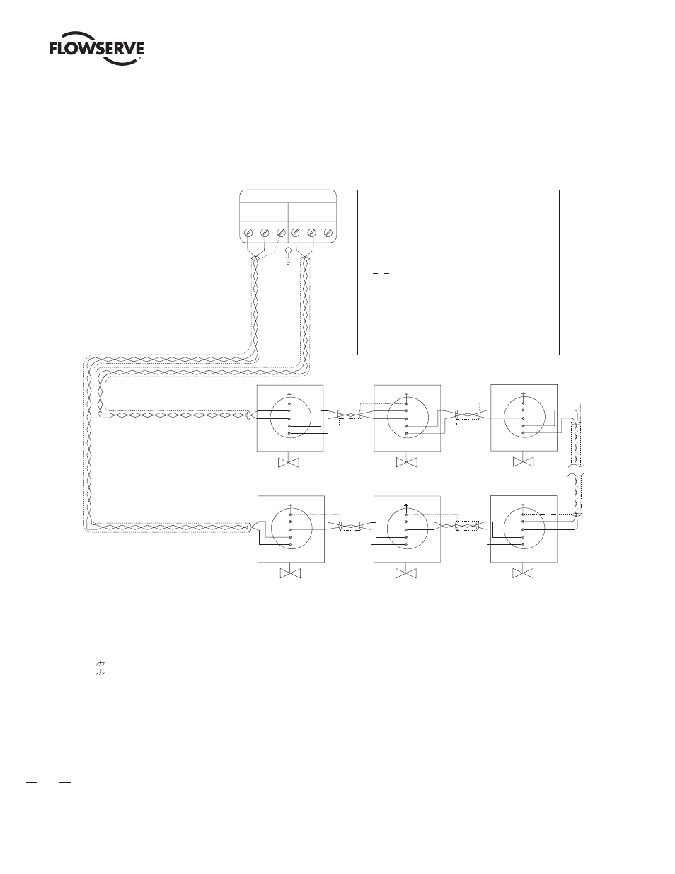
4.4 Master Station Network Topologies
Notes:
1) Belden 3074F, 3105A, or 9841 shielded cable is recommended.
2) Correct polarity for field unit and network controller
connection is necessary for proper operation.
3) Connections shown are typical. The number of
MOVs shown may not indicate true system size.
4)
Earth ground: ground rod
5)
Earth ground: ground rod or lug in
actuator if actuator is grounded.
Channel A
Channel B
MASTER STATION III
A1*
MOV-1
See Note 5
A2*
N/C
MOV-249
See Note 5
N/C
MOV-3
See Note 5
N/C
4
5
14
3
3
3
3
3
3
13
A2
A1
A1*
A2*
4
5
14
13
A2
A1
A1*
A2*
4
5
14
13
A2
A1
N/C
N/C
MOV-2
See Note 5
A1*
A2*
4
5
14
13
A2
A1
MOV-248
See Note 5
A1*
A2*
4
5
14
13
A2
A1
MOV-250
See Note 5
A1*
A2*
4
5
14
13
A2
A1
Diagnostic Note:
Polarity and level of the network’s data connection
can be checked by measuring voltage between data
and data* terminals. This voltage should be greater
than +200 mV DC with network controller (host)
network ports disconnected. Data terminal is
positive with respect to data* terminal.
Earth Ground Note:
If low impedance earth ground is not available at each
actuator, contact engineering for alternative earth
ground surge protection strategies.
Legend
MOV
N/C
Data terminal is positive with respect to
data* terminal
13
14
5
4
- Motor-operated valve
- Data A1
- Data A1*
- Data A2
- Data A2*
- Shield
- No connection
Figure 4.6 - Modbus Redundant Loop Topology