Limitorque actuation systems – Flowserve DDC-100 Master Station II User Manual
Page 40
40
DDC-100 Master Station II Installation and Operation Manual
FCD LMAIM5001-00
Flow Control Division
Limitorque Actuation Systems
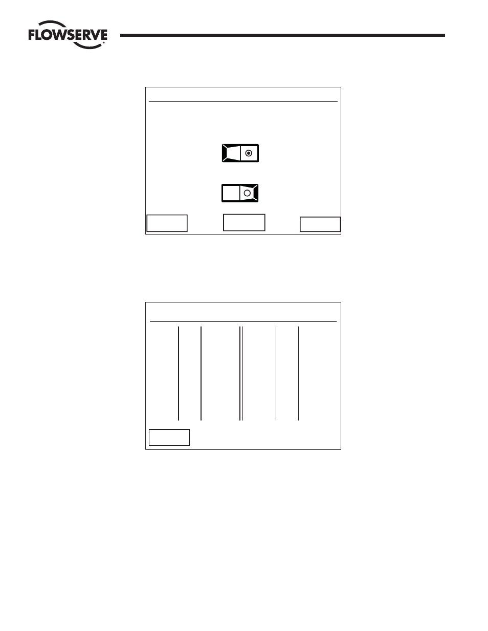
Figure 7-11: The Writer Holding Register screen
When the users selects the number of command registers to be mapped into the DCS Data table, the
toggle switch will display a green dot. Once the selections have been completed, touching the “View >>”
button will display a sample Data Table for the first 12 control or command registers (Figure 7-13).
Figure 7-12: Sample Data Table for Modbus Function Code 06/16
Limited to two registers per write with the Modus Function code, 16. Touching the “<< Back” button will
take the user to the Write Register selection screen where the chosen register format may be saved or
altered to another configuration (Figure 7-12). Selecting a register for a specific field unit follows the
convention listed on the next page.
DCS Requested Write Register = [(field unit address –1) * number of registers per unit] + desired register
Data Table Modbus Function Code 06
Reg.# MOV# Meaning
45001 1 CMD
45002 2 CMD
45003 3 CMD
45004 4 CMD
45005 5 CMD
45006 6 CMD
45007 7 CMD
45008 8 CMD
45009 9 CMD
45010 10 CMD
45011 11 CMD
45012 12 CMD
Reg.# MOV# Meaning
<< Back
Modbus Holding Registers
Select Desired Number of
Write Holding Registers
1/MOV
2/MOV
Store
View >>
<< Back