Hot standby configuration – Flowserve DDC-100 Master Station II User Manual
Page 51
FCD LMAIM5001-00
DDC-100 Master Station II Installation and Operation Manual
51
Flow Control Division
Limitorque Actuation Systems
10
Hot Standby Configuration
10.1
Overview
The Master Station is capable of Hot Standby Operation. Two identical processing units communicate with
each other via an Ethernet 10-BaseT connection. One processing unit is configured to be “Hot” while the
other unit is configured to be “Standby.”
10.2
Configuration
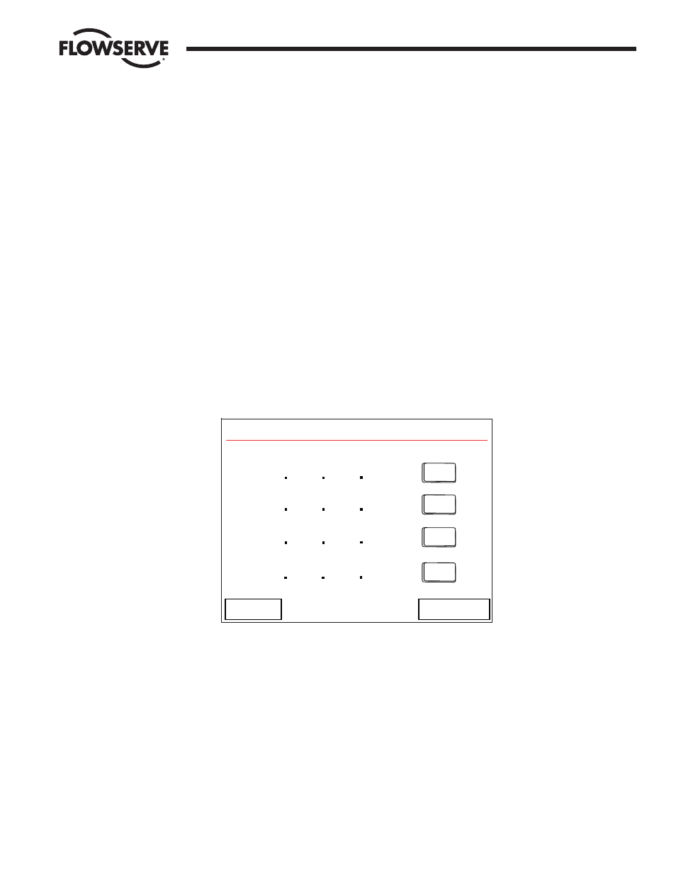
Each unit must be configured for TCP/IP communication. This is accomplished via the HMI interface on
the “Configure Ethernet Port” screen (Figure 10-1).
Figure 10-1: The Configure Ethernet Port screen
In addition, the “Hot Standby IP Address” must be configured with the other processing unit’s IP address.
For example, the Hot processing unit must have the Standby processing unit’s IP address in the “Hot
Standby IP Address” section, and the Standby processing unit must have the Hot processing unit’s IP
address in the “Hot Standby IP Address” section.
IP addresses are configured by touching the “Edit” button on the row of the address to be configured.
This will allow the user to set the octets of the IP address from the left to the right, one octet at a time.
Use the “Next” and “Back” buttons on each editing screen to navigate between screens.
Following the successful configuration of the IP address information for each unit, further configuration is
necessary.
The “Configure Hot Standby” screen of the HMI (Figure 10-2) allows the user to configure the startup
mode of each processing unit, displays the current state of each processing unit (i.e. Idle, Standby, or
EDIT
EDIT
EDIT
EDIT
EDIT
EDIT
EDIT
EDIT
<< Back
Top Screen
IP Address
192 168
0 100
Mask
255 255 255
0
Gateway
192
168
0
1
Hot Standby IP Address
192 168
0 101
Configure Ethernet Port