Flowserve MX Electronic Actuator User Manual
Page 24
Limitorque MX Electronic Actuator FCD LMENIM2306-06 – 10/13
24
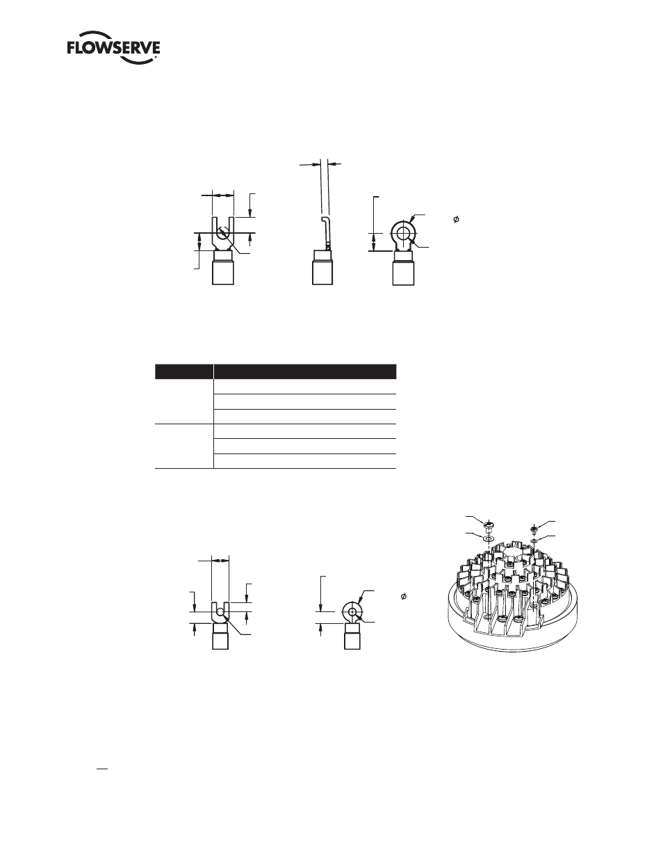
Figure 3.10 – Power terminal connector size limitations
NOT TO
EXCEED 15
NOT TO
EXCEED 6.5
NOT TO
EXCEED 9.8
TO BE SIZED
FOR M5 SCREW
SPADE AND SNAP
TERMINALS
MAX. THICKNESS = 1.6 mm
TO BE SIZED
FOR M5 SCREW
NOT TO
EXCEED 9.6
NOT TO
EXCEED 15
RING TERMINAL
NOT TO
EXCEED 3.5
FLANGED
SPADE TERMINAL
Figure 3.11 – Terminal block rating; power terminals
Description
L1
L2
L3
STD Rating
30 AMP
20 AMP
15 AMP
8 Awg/10 mm
2
10 Awg/6 mm
2
14 Awg/2.5 mm
2
600 VAC
RMS
150 VDC
Increased
Safety Rating
27 AMP
18 AMP
13.5 AMP
8 Awg/10 mm
2
10 Awg/6 mm
2
14 Awg/2.5 mm
2
500 VAC
RMS
150 VDC
Note: Ratings will be the same for L1, L2, or L3, e.g., if 10 Awg is selected,
then L1, L2 and L3 will have the same limitations.
Figure 3.12 – Control terminal connector size limitations
NOTE: All dimensions are in mm.
NOTE: Limitorque recommends the use of the following connector for optimum results: Thomas and Betts #RZ22-6.
NOTE: Alternative manufacturers may be substituted only if the dimensions are in accordance with Figure 3.12.
Table 3.2 lists the maximum allowable voltage and current parameters for the terminal block control terminals.
NOT TO
EXCEED 4.0
NOT TO
EXCEED 7.6
NOT TO
EXCEED 5
TO BE SIZED
FOR M3 SCREW
SPADE AND SNAP
TERMINAL
MAX. THICKNESS = 1.0 mm
NOT TO
EXCEED 5
TO BE SIZED
FOR M3 SCREW
RING TERMINAL
NOT TO
EXCEED 8.2
3X M5 SCREW
3X M5 SPRING
WASHER
54X M3 SPRING
WASHER
54X M3 SCREW
FIGURE 3.13
THE USE OF THE SPRING WASHERS ARE REQUIRED
ON INCREASED SAFETY APPLICATIONS.