4 terminal block shield installation, 5 commissioning the actuator, 11 hart installation wiring – Flowserve MX Electronic Actuator User Manual
Page 31: 12 replacing terminal cover, 13 external earth/ground connections
31
Limitorque MX Electronic Actuator FCD LMENIM2306-06 – 10/13
flowserve.com
Please refer to Table 3.4 for connections.
3.3.11 HART Installation Wiring
HART, or Highway Addressable Remote Transducer, is a digital signal over analog 4-20 mA communications. Please
consult LMENIM2340, HART Network Installation and Operation Manual for correct wiring preparation and installation.
3.3.12 Replacing Terminal Cover
Verify that the O-ring seal and spigot joint are clean and in good condition. Lightly coat these items with mineral-based
lubricant before replacing the terminal cover and four retaining screws.
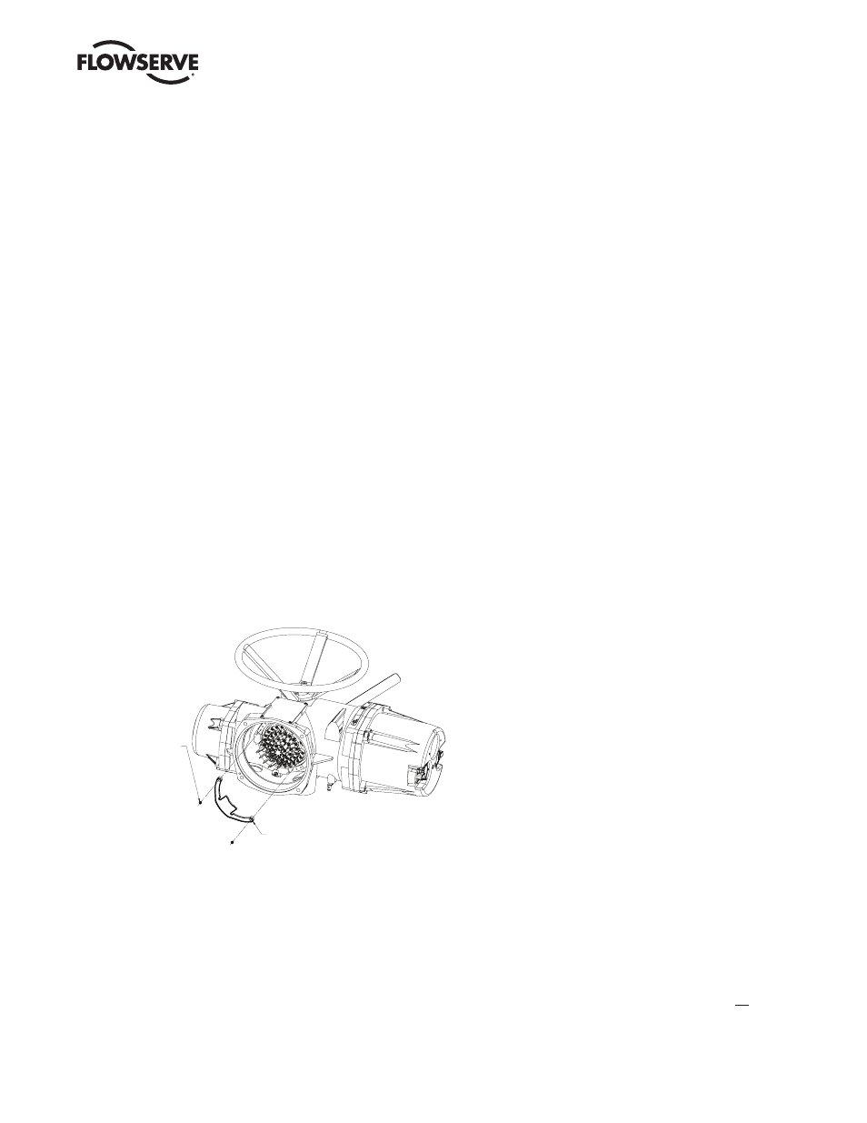
3.3.13 External Earth/Ground Connections
In order to help meet the local electric codes of the installation, one external connection point is provided on the main
gear housing for the attachment of earth/ground cables. See Figure 3.21. This is in addition to the ground connection
inside the terminal compartment.
3.4 Terminal Block Shield Installation
STEP 1
Remove terminal block cover.
STEP 2
Use Qty of 2 screws from terminal block or from end users bag to attach shield.
STEP 3
Remount terminal block cover.
Figure 3.19 – Terminal block shield
M3 X 5 SELF LOCK
SCREW
USE QTY. OF TWO (2)
TO MOUNT SHIELD.
USE 2 SCREWS FROM
TERMINAL BLOCK OR
FROM END USERS
BAG.
SHIELD-TERMINAL BLOCK
3.5 Commissioning the Actuator
Before attempting to commission the actuator, verify that the actuator is installed correctly on the valve and main power
is “ON.”
After making the initial electrical connections detailed in Section 3.3, Electrical Connections, the MX actuator may be
commissioned without removing any covers. No special tools are required. Configuration is accomplished through the
use of the LCD and the control knobs mounted on the control panel.
For positioning the actuator:
1. Place the red knob in the “LOCAL” position.
2. Move the black knob to the “OPEN” or “CLOSE” position.