Fluke Biomedical 8000 Victoreen User Manual
Page 40
Victoreen 8000
Operators Manual
2-28
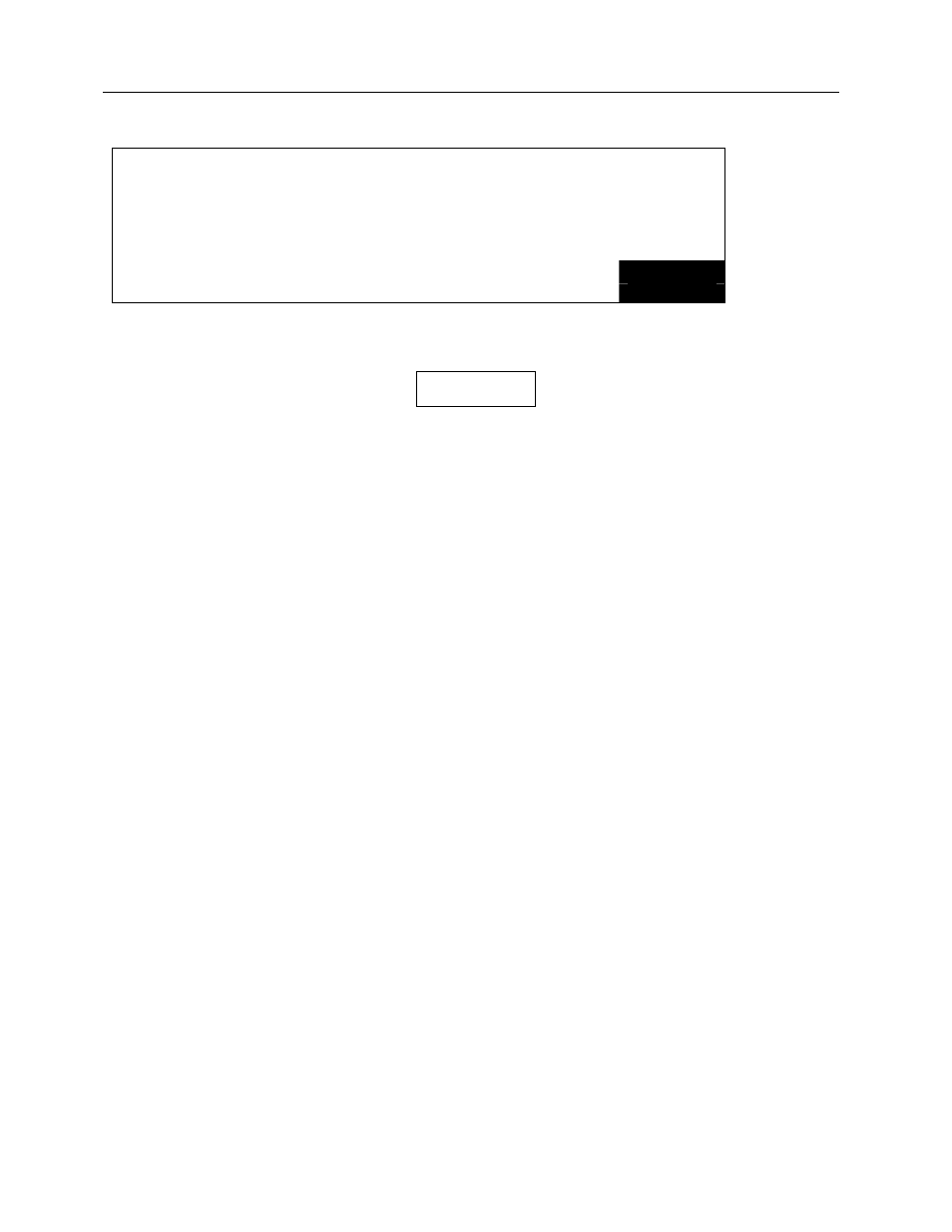
65.6
kVp Avg
57
msec/frame
65.0
kV Eff
250.9
mR/frame
67.2
kV Peak
45.6
mAs/frame
AMSE LOW
MAKE
MODE SENS
EXPOSURE
The NERO mAx is now ready to take another exposure. Pressing the mode key at any time exits from
this measurement mode and returns to the mode selection screen.
NOTE
The exposure rate displayed after the SAVE key
has been pressed may be slightly different from the
rate displayed before the stop key was pressed.
This is because the exposure rate is calculated
based upon correction factors that are based upon
the measured kVp. In the AMSE mode, kVp is not
measured until after the SAVE key is pressed, so a
constant is used to calculate exposure and rate.
The constant that is used is based upon the
calibration factors corresponding to a kVp average
of the mid point of the selected filter range. After
the SAVE key is pressed, the NERO mAx
calculates kVp and applies an exposure correction
factor based upon the calculated kVp.
As a power saving feature, the NERO mAx’s display backlight turns off after one minute of no activity.
The backlight turns back on when any button is pressed or an exposure is made. In addition, after five
minutes of no activity, the NERO mAx exits from any measurement mode and returns to the mode
selection screen.
2.5.5 CT Exposure Mode
CT Exposure mode is used to make CT exposure measurements using the Victoreen 6000-100 or 6000-
200 CT ion chamber. A CT probe must be connected to the 8000 detector’s external ion chamber input
in this mode. The exposure is calculated using the user entered beam width (in mm) and the CT probe’s
calibration factor (Rcm/nC). This mode functions in the same manner as the Exposure Mode with the
addition of beam width entry.
To make a CT exposure measurement
Make sure that the NERO mAx is turned off. Plug one end of the NERO mAx’s detector cable into the
NERO mAx detector. Plug the other end of the detector cable into the NERO mAx’s detector connector.
No filter card needs to be present in the detector. Plug the CT chamber’s BNC connector into the ion
chamber signal input at the rear of the NERO mAx detector. Plug the CT chamber’s bias plug (banana
jack) into the bias output at the rear of the NERO mAx detector. Position the ion chamber as needed.
If results are to be printed, plug the printer cable into the printer port at the rear of the NERO mAx then
plug the other end of the printer cable into the printer and turn the printer on (see Section 1.5--Printing).