Model chart – GAI-Tronics ICP9000 Navigator Series Console Operator's Manual User Manual
Page 9
ICP9000 Navigator Series Console Operator’s Manual
Foreword
9
12/10
Model Chart
The Main Control Unit (MCU) model number, located on the nameplate on the end of the unit (could be
the bottom or side, depending on mounting configuration), specifically identifies GAI-Tronics’
equipment. The last two digits in the model number indicate the number of channels available within
that specific unit (04A = 4 channels, 08A = 8 channels, 12A = 12 channels). Factory-installed options
are identified in the display area of the Navigator PC screen upon the initial application of power.
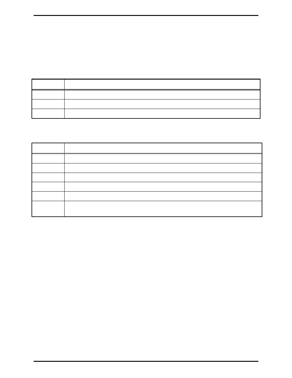
The following is a list of the ICP9000 Navigator models:
Model Description
ICPN9004A 4-Channel
Navigator Series MCU (expandable)
ICPN9008A 8-Channel
Navigator Series MCU (expandable)
ICPN9012A
12-Channel Navigator Series MCU
The following options may be ordered pre-installed in your ICP9000 Navigator Series Console:
Options Description
CP0010
DC Control (Order one for each dc channel)
CP0040
E&M Signaling (One option for every four channels – requires CP0050)
CP0050 Supervisory
Control
CP0060
External Enhanced Full Duplex Phone Interface
CP0070
Direct Enhanced Full Duplex Phone Interface
CP0650
MDC1200 STAT-ALERT Signaling (Not compatible with Logging Recorder Output
Module)
The following features are included in the standard console and are available through either
programming selection or direct access:
• DTMF Decode
• Positive Mode Control
• Paging Encode
• Multi-Select Option
• 16-Frequency Capability
• Logging Recorder Output