Step 7 evacuate and charge the coil, Step 8 install the drain line, Step 6 check coil piping for leaks – Greenheck DG / DGX with Direct Spark (464043 IOM) (Pre-2008) User Manual
Page 16: Step 5 mount the remote sensing bulb (by others), Important
16
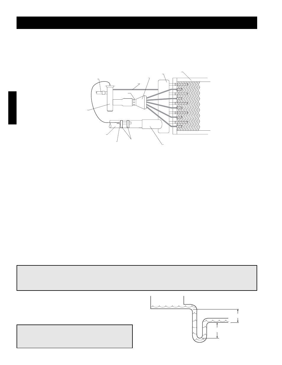
Installation - Direct Expansion (DX) Coil Piping (Optional)
Installation
Step 7 Evacuate and Charge the Coil
Use a vacuum pump to evacuate the coil and any interconnecting piping that has been open to the atmosphere.
Measure the vacuum in the piping using a micron gauge located as far from the pump as possible. Evacuate the
coil to 500 microns or less then close the valve between the pump and the system. If the vacuum holds to 500
microns or less for one minute, the system is ready to be charged or refrigerant in another portion of the system
can be opened to the coil. A steady rise in microns would indicate that moisture is still present and that the coil
should be further vacuumed until the moisture has been removed.
6 in. min.
6 in. min.
Step 8 Install the Drain Line
Connect an unobstructed drain line to the drain pan.
A trap should be used to prevent sewer gas from
being drawn into the unit.
NOTE!
Failure to obtain a high vacuum indicates a great deal of moisture or a small leak. Break the vacuum
with a charge of dry nitrogen or other suitable gas and recheck for leaks. If no leaks are found,
continue vacuuming the coil until the desired vacuum is reached.
Step 6 Check Coil Piping for Leaks
Pressurize the coil to 100 psig with dry nitrogen or other suitable gas. The coil should be left pressurized for a
minimum of 10 minutes. If the coil holds the pressure, the hook-up can be considered leak free. If the pressure
drops by 5 psig or less, re-pressurize the coil and wait another 10 minutes. If the pressure drops again there is
likely one or more small leaks which should be located and repaired. Pressure losses greater than 5 psig
indicate a large leak that should be isolated and repaired.
Step 4 Install the Liquid Line and Thermal Expansion Valve (TEV) (By Others)
Liquid line openings vary by coil size and circuiting and are field supplied. Follow the TEV recommendations for
installation to avoid damaging the valve. If the valve is externally equalized, use a tubing cutter to cut off the
plugged end of the factory installed equalizer line. Use a de-burring tool to remove any loose metal from the
equalizer line and attach it to the TEV. If the valve is internally equalized, the factory installed equalizer line can
be left as is.
Step 5 Mount the Remote Sensing Bulb (By Others)
The expansion valve’s remote sensing bulb should be securely strapped to the horizontal run of the suction line
at the 3 or 9 o’clock position and insulated.
IMPORTANT!
All traps must be installed below the roofline or
be otherwise protected from freezing.
Drain Trap
Coil
Suction Header
Distributor
Equalizer Line
Nozzle
Liquid Line
Expansion Valve
Suction Line
Remote Sensing Bulb
Straps
Suction Connection
General Installation
(by others)