I/o interface, Edge-ti internal circuitry, Example inputs – Hypertherm Shape Cutting Control User Manual
Page 32: Example outputs, External circuitry, Outputs external circuitry, Inputs
Edge Ti
26
Input Mode
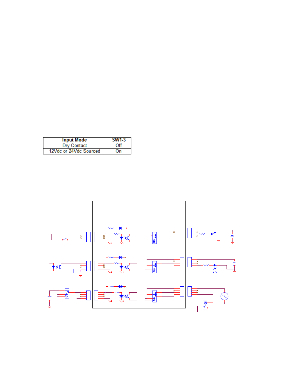
Note that the inputs have two different modes that are selectable using DIP
switch SW1-3. When this switch is OFF the inputs are in the sourced input mode
and an external voltage source of between 12V and 24V is required to activate
each input.
When DIP switch SW1-3 is ON, the inputs are all in the dry contact mode and
require an external switch to common to activate the inputs. The logic states
sensed by the CNC are reversed between the two input modes.
In a sourced input circuit, an inactive input will produce a logic low and an active
input will produce logic high. In dry contact mode these logic levels are reversed
with an inactive input producing logic high and an active input producing a logic
low.
Switch SW1-3
I/O Interface
The following illustration shows the details of connecting the I/O to common
circuitry. All outputs are relay contacts rated at 1 AMP 250VAC maximum
RESISTOR
LED
12V
Use External +12V Supply
& normally Closed Contact
24V
+
GND_External
+
RESISTOR
Use External +5V Supply
& normally Open Contact
RELAY SPDT
Normal Sourced Inputs
Use External +24V Supply
GND_External
5V
NC
NO
+
COM
12V
GND_External
GND_External
RELAY
GND
External Circuitry
OPTO ISOLATOR
+
Use External 120 Vac
& normally open contact
RELAY SPDT
COM
NO
NC
3900
RELAY SPDT
NC
COM
NO
Dry Contact Inputs
Note: Logic Level Reversal
SWITCH
Normal Sourced Inputs
DIP Sw 1-C Open
Edge-Ti Internal Circuitry
Outputs
External Circuitry
OPTO ISOLATOR
Inputs
GND
3900
Example Inputs
3900
GND
3900
3900
Open
Open
+24V Field
3900
RELAY
120 Vac
Normal Sourced Inputs
Use External +12V Supply
Normal Sourced Inputs
DIP Sw 1-C Open
Dry Contact Inputs
DIP Sw 1-C Closed
GND_External
Example Outputs