Hypertherm MAX200 Service Manual User Manual
Page 158
Advertising
MAX200
Service Manual
4-63
PARTS LIST
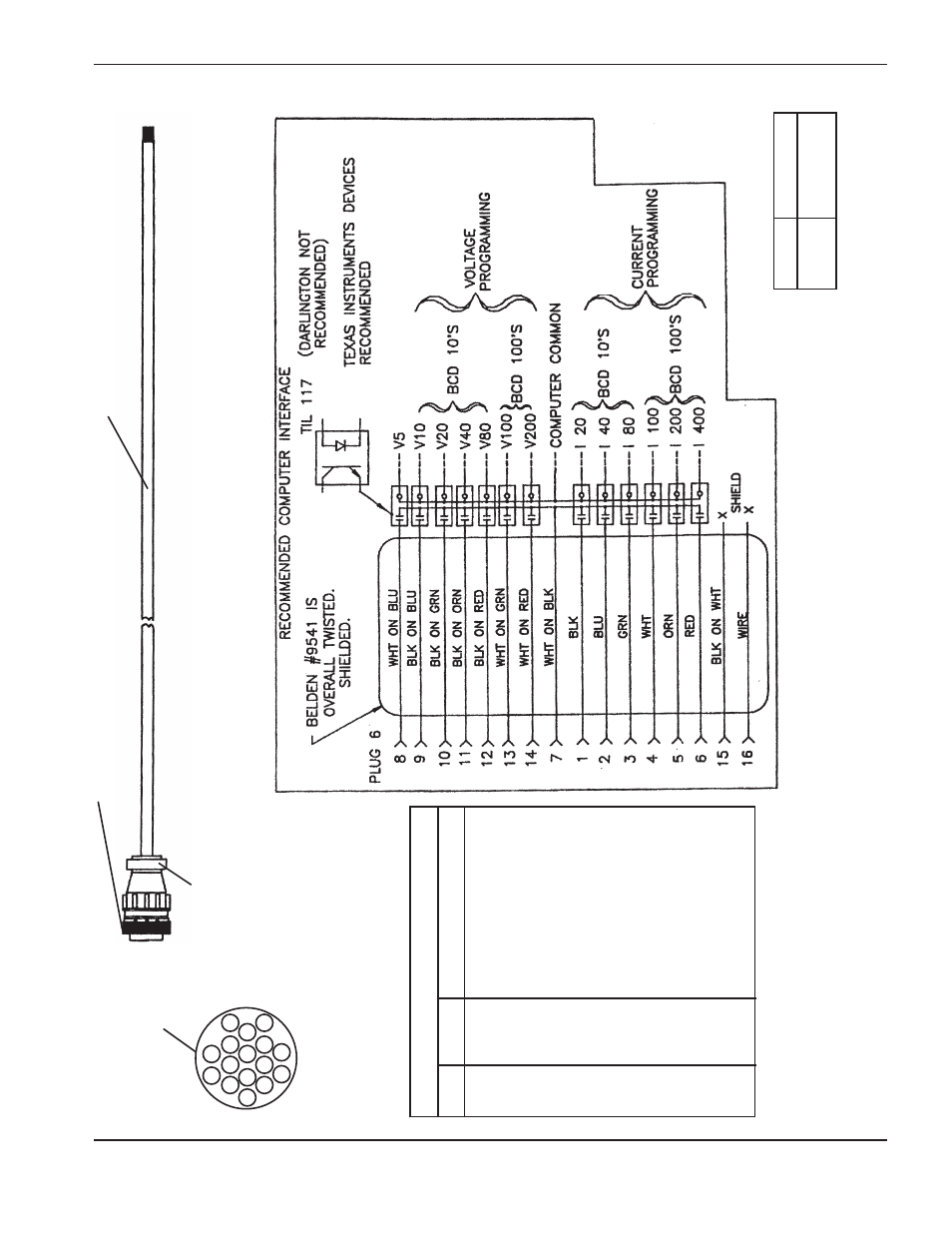
15
Figure 4-27
Computer Cable – Programmable Remote (PR) V/C to Computer Interface
Programmable Remote End
SCKT
COLOR
F
UNCTION
1
B
lk
Current Program –
I 20
2
B
lu
" "
I
4
0
3
G
rn
" "
I
8
0
4
W
h
t
" "
I
1
0
0
5
O
rn
" "
I
2
0
0
6
Red
" "
I
400
7
W
ht/Blk
Common (RemoteChassis)
8
W
ht/Blu
V
oltage Program –
V
5
9
B
lk/Blu
" "
V
10
10
Blk/Grn
" "
V
20
1
1
Blk/Orn
" "
V
40
12
Blk/Red
" "
V
80
13
Wht/Grn
" "
V
100
14
Wht/Red
" "
V
200
15
Blk/Wht
S
pare (Remote Chassis)
16
Shield
Shield (Remote Chassis)
12
15
16
1
1
12
13
14
345
6
78
9
1
0
008186 Socket (16)
REAR VIEW
008192 Strain Relief
008191 Plug,
Shell 17-16 Size
5X2
047025 Cable 24-15 Shielded
Cutting Machine Computer
Part No.
L
ength
023099
25 ft ( 7.6m)
023100
50 ft (15m)
Advertising
See also other documents in the category Hypertherm Equipment:
- EDGE Pro Ti Shape Cutting Control Rev.2 (288 pages)
- 80669J Rev.3 (304 pages)
- HD3070 Plasma Arc Cutting System w/ Manual Gas Console (281 pages)
- MAXPRO200 Rev.2 (294 pages)
- MicroEDGE Pro Shape Cutting Control Rev.2 (182 pages)
- HPR260 Auto Gas Preventive Maintenance Program Rev.4 (288 pages)
- Powermax1650 (317 pages)
- Shape Cutting Control (66 pages)
- PHC Sensor (58 pages)
- HTA Rev 6.00 Operators Manual (212 pages)
- HTA Rev 7.00 Install Guide (242 pages)
- THC Control Board Replacement (13 pages)
- THC Plasma Interfacer Upgrade (9 pages)
- THC X-Y Table Product Configuration (20 pages)
- D845GERG2 (128 pages)
- MRT2 (64 pages)
- MRT (98 pages)
- Duramax Hyamp Long Handheld Torches (92 pages)
- Duramax Hyamp Robotic Torch (74 pages)
- HyIntensity Fiber Laser Rev.3 (240 pages)
- PCBS-0124 (70 pages)
- SuperMicro 370SBA 533Mhz (90 pages)
- LR2075 (56 pages)
- Phoenix 8.0 (585 pages)
- LH2125 (60 pages)
- HD3070 w/ Automatic Gas (35 pages)
- HD3070 w/Manual Gas (43 pages)
- HD4070 Rev.8 (278 pages)
- HD4070 Product Configuration (88 pages)
- HPR800XD Manual Gas Preventive Maintenance Program Rev.1 (33 pages)
- HPR800XD Manual Gas Preventive Maintenance Program Rev.1 (32 pages)
- HPR800XD Manual Gas Rev.2 (368 pages)
- HPRXD Short Torch with Integrated Lead Rev.1 (30 pages)
- HT4001 (59 pages)
- DuraChill 5 HP Air-Cooled Chiller For Hypertherm (29 pages)
- HT4001 Air Injected Water Muffler System (40 pages)
- H601 Power Supplies (62 pages)
- MAX200 Remote Switch (9 pages)
- HT4100 Plasma Arc Cutting System Operating (50 pages)
- HT4001 Plasma Arc Cutting System (259 pages)
- HSD130 HySpeed Plasma (233 pages)
- HySpeed HT2000 Plasma Arc Cutting System Rev.7 (53 pages)
- HySpeed HT2000 Plasma Arc Cutting System Rev.27 (289 pages)
- MAX200 Water Muffler (39 pages)
- HT2000LHF Product Configuration (23 pages)