Hypertherm MAX200 Service Manual User Manual
Page 58
MAX200
Service Manual
3-17
1-97
MAINTENANCE
3.
The green POWER ON
pushbutton switch PB1 is
pressed, the fans are operating,
but the green POWER ON
indicator does not illuminate.
3.1. Pushbutton PB1 was not held down long enough.
Press and hold PB1 for a minimum of five seconds.
3.2. Relay CR1 on the Power Distribution Board is defective.
Check that CR1 switches when POWER ON pushbutton is
pressed. See Figure 3-2 for location of CR1. If CR1 is
defective, desolder CR1 and replace.
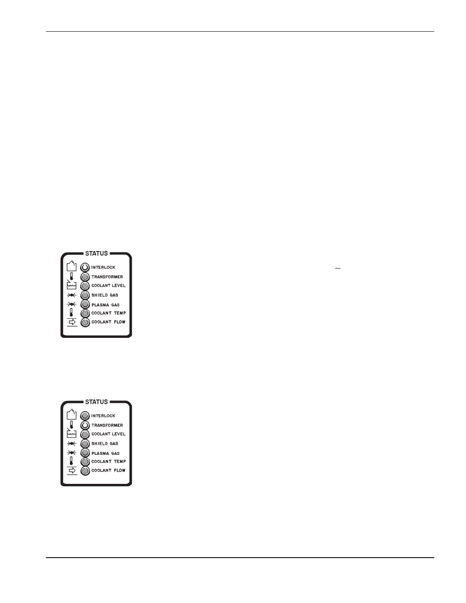
3.3. One or more of the STATUS LEDs remains illuminated,
indicating a fault condition.
The following is a guide to troubleshooting the cause of unlit
STATUS indicators:
3a.
INTERLOCK LED
illuminated:
3a.1. No jumper between terminals 34 and 35 of TB4.
If your unit does not have a Remote High Frequency
Console, this LED will be satisfied if there is a jumper
between terminals 34 and 35 of TB4. See Figure 4-10 for
location of TB4. If the jumper is there:
• Using the 013-2-179 wiring diagram, check pins,
connectors and associated wiring from REC3 on the
Power Distribution Board (PCB6) to terminals 34 and 35
of TB4.
Repair and/or replace defective component(s) if necessary.
3b.
TRANSFORMER LED
illuminated:
3b.1. Main transformer T2 or one of the choppers is
overheating.
This LED will extinguish when the main transformer (T2) is
operating in a normal temperature range (under 165° C)
and choppers CH1 and CH2 are also operating in the
normal temperature range (under 82° C). See Figure 4-3
for location of T2 and connector to TS1. Chopper
temperature switches TSW1 and TSW2 are located on
choppers CH1 and CH2 respectively. See Figures 4-7, 4-8
and 4-9.
Problem
Possible Causes and Solutions
/CAP
/CAP