Hypertherm MAX200 Service Manual User Manual
Page 61
3-20
MAX200
Service Manual
1-97
MAINTENANCE
3e.2. Pressure switch PS1 not functioning.
This switch is normally open, and closes when plasma gas
pressure is at or above 60 psi. After PS1 is closed, the
12 VDC extinguishes the PLASMA GAS LED.
• Using the 013-2-179 wiring diagram, check pins,
connectors and associated wiring from REC3 on the
Power Distribution Board to PS1.
Repair and/or replace defective component(s) if necessary.
3f.
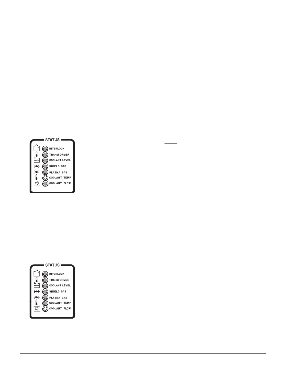
COOLANT TEMP LED
illuminated:
3f.1. Coolant too hot.
This LED will extinguish when temperature switch TS2
senses that the temperature of coolant in the coolant
reservoir is under 160°F. See Figure 4-13 for location of
TS2 and the coolant reservoir.
• Check to see if water coolant is above 160°C.
• Disconnect PL24 (located in the rear of the power supply
near the coolant reservoir), and check to see if TS2 is
open. TS2 is normally closed, and is opened when a
temperature above 160°F is reached.
• Using the 013-2-179 wiring diagram, check pins, wires
and connections from PL24 to REC3 of PCB6. See Figure
4-6 for location of PCB6. See Figure 3-2 for location of
REC3.
Repair and/or replace defective component(s) if necessary.
3g.
COOLANT FLOW LED
illuminated:
3g.1. Coolant flow too slow.
This LED will extinguish when FS1 senses a coolant flow
of at least .5gpm to the torch. See Figure 4-13 for location
of flow switch FS1, motor M1, pump P1 and filter element.
3g.2. Motor M1 not functioning.
• Check to see if 240VAC is available at PL21. PL21 is
located near the pump. Note: The 240VAC relay (CR3) on
PCB6 will not close until the first five interlocks (STATUS
indicators) are satisfied.
Problem
Possible Causes and Solutions
/CAP
/CAP