Hypertherm MAX200 Service Manual User Manual
Page 59
3-18
MAX200
Service Manual
1-97
MAINTENANCE
• Check temperature switches (normally closed).
• Check pins, connectors and associated wiring to
temperature switches.
• Leave the fans running, and try restarting the unit after
one hour. If LED still illuminates, one of the choppers or
the main transformer may need to be replaced.
3c.
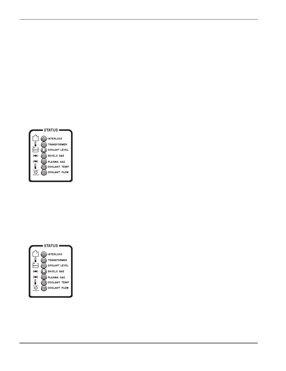
COOLANT LEVEL LED
illuminated:
3c.1. Coolant level is low.
This LED will extinguish when a proper coolant level in the
coolant reservoir is maintained. Level switch LS1 is
located in the coolant reservoir, and will open when it
senses that coolant level is too low. See Figure 4-13 for
location of coolant reservoir and LS1.
• Check coolant level.
• If coolant level is adequate, disconnect PL23 (located
near reservoir) and check to see if LS1 switch is closed.
• Check connections and associated wiring from PL23 to
REC3 of PCB6. See Figure 4-6 for location of PCB6, and
Figure 3-2 for location of REC3.
Repair and/or replace defective component(s) if necessary.
3d.
SHIELD GAS/CAP LED
illuminated:
3d.1. Shield gas pressure too low.
This LED will extinguish when shield gas pressure of
70 psi or greater is sensed by PS2. See Figure 4-6 for
location of PS2, and Figure 3-14 for gas interconnect
diagram.
• Check to see that shield gas supply is set to
specifications according to the Cut Chart tables in
Section 4 of MAX200 Instruction Manual (#800870 Hand
Torch; #800980 Machine Torch).
• Verify that all shield gas connections are secure, and that
there are no leaks in the hosing. See Figure 4-10 for
location of Shield Gas Supply bulkhead.
Problem
Possible Causes and Solutions
/CAP
/CAP