Hypertherm MAX200 Service Manual User Manual
Page 56
Advertising
MAX200
Service Manual
3-15
8-99
MAINTENANCE
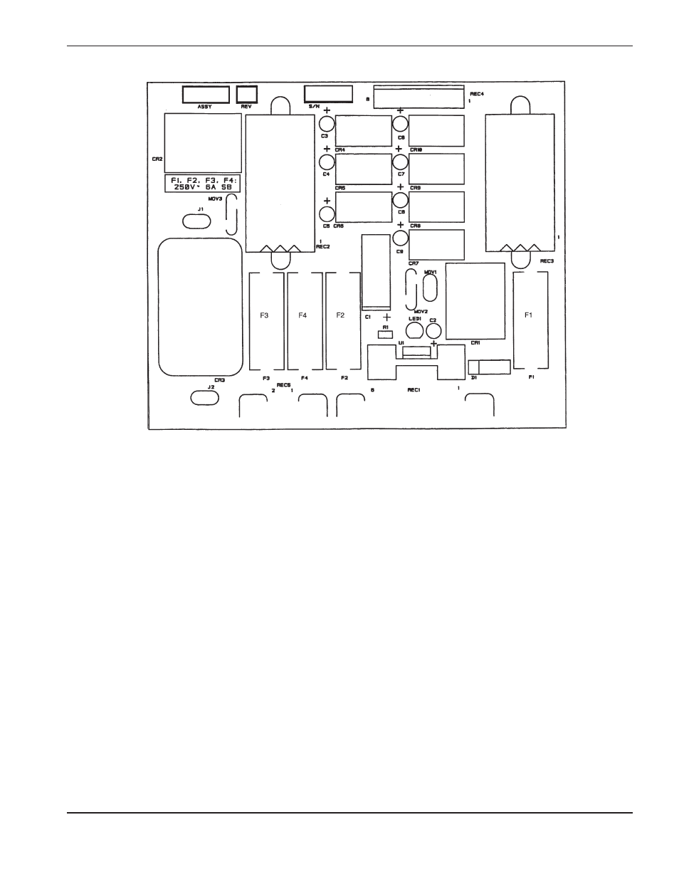
6. Measure voltage at power distribution board PCB6 (Figure 3-1, item 1). Look on the board for fuses F1 through
F4 (Figure 3-2). Measurements between each fuse and chassis ground should be as follows:
F1:
24VAC
F2:
120VAC
F3:
240VAC
F4:
120VAC
If voltages are not present, or incorrect at 1 or more of these points, disconnect power and troubleshoot PCB6
fuses and associated pins, connectors and wiring between power distribution board connector REC1 and
transformer secondary T1 (Figure 3-1, item 6).
Also, check main power fuses F1 and F2 (Figure 3-1, item 3) and associated wiring and connections between
T1 and L1 and L2.
Repair or replace any defective components.
Figure 3-2
Power Distribution PCB6
Advertising
See also other documents in the category Hypertherm Equipment:
- EDGE Pro Ti Shape Cutting Control Rev.2 (288 pages)
- 80669J Rev.3 (304 pages)
- HD3070 Plasma Arc Cutting System w/ Manual Gas Console (281 pages)
- MAXPRO200 Rev.2 (294 pages)
- MicroEDGE Pro Shape Cutting Control Rev.2 (182 pages)
- Powermax1650 (317 pages)
- HPR260 Auto Gas Preventive Maintenance Program Rev.4 (288 pages)
- Shape Cutting Control (66 pages)
- PHC Sensor (58 pages)
- HTA Rev 6.00 Operators Manual (212 pages)
- HTA Rev 7.00 Install Guide (242 pages)
- THC Control Board Replacement (13 pages)
- THC Plasma Interfacer Upgrade (9 pages)
- THC X-Y Table Product Configuration (20 pages)
- D845GERG2 (128 pages)
- MRT2 (64 pages)
- MRT (98 pages)
- Duramax Hyamp Long Handheld Torches (92 pages)
- Duramax Hyamp Robotic Torch (74 pages)
- HyIntensity Fiber Laser Rev.3 (240 pages)
- PCBS-0124 (70 pages)
- SuperMicro 370SBA 533Mhz (90 pages)
- LR2075 (56 pages)
- Phoenix 8.0 (585 pages)
- LH2125 (60 pages)
- HD3070 w/ Automatic Gas (35 pages)
- HD3070 w/Manual Gas (43 pages)
- HD4070 Rev.8 (278 pages)
- HD4070 Product Configuration (88 pages)
- HPR800XD Manual Gas Preventive Maintenance Program Rev.1 (32 pages)
- HPR800XD Manual Gas Preventive Maintenance Program Rev.1 (33 pages)
- HPR800XD Manual Gas Rev.2 (368 pages)
- HPRXD Short Torch with Integrated Lead Rev.1 (30 pages)
- HT4001 (59 pages)
- DuraChill 5 HP Air-Cooled Chiller For Hypertherm (29 pages)
- HT4001 Air Injected Water Muffler System (40 pages)
- H601 Power Supplies (62 pages)
- MAX200 Remote Switch (9 pages)
- HT4100 Plasma Arc Cutting System Operating (50 pages)
- HT4001 Plasma Arc Cutting System (259 pages)
- HSD130 HySpeed Plasma (233 pages)
- HySpeed HT2000 Plasma Arc Cutting System Rev.7 (53 pages)
- HySpeed HT2000 Plasma Arc Cutting System Rev.27 (289 pages)
- MAX200 Water Muffler (39 pages)
- HT2000LHF Product Configuration (23 pages)