LSC Lighting maXim S User Manual
Page 11
maXim S & M
Operator Manual V3
LSC Lighting Systems (Aust) Pty. Ltd
Page 7
4
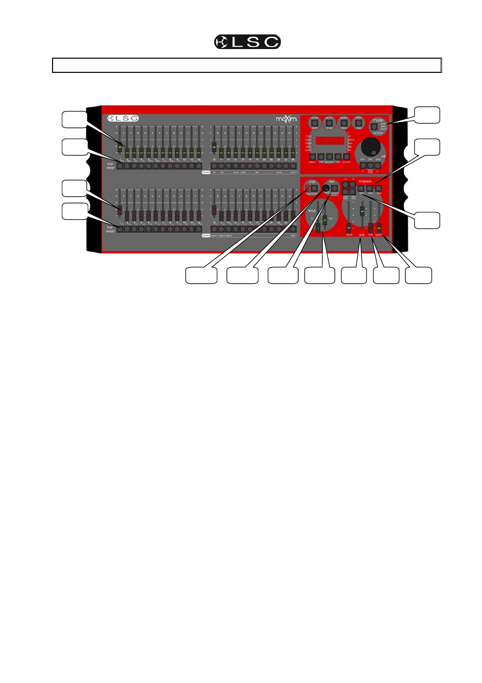
FRONT PANEL TOUR
The diagram below shows a maXim M. The maXim S is similar but has fewer red and yellow faders.
4.1
YELLOW BANK FADERS
Control the levels of channels 1 to 12 (24)
respectively.
4.2
YELLOW BANK MASTER
• Controls the overall level of the Yellow bank
faders.
• In WIDE mode, it controls the overall level of
the single wide preset consisting of the Yellow
bank faders and the Red bank faders.
4.3
MODE RED BANK BUTTON
Selects the current function for the RED bank
faders. The choices are;
• preset.
• wide.
• p'back
(playback).
4.4 RED
BANK
FADERS
The Red bank of faders has different functions
depending upon the current “MODE” as selected
by the mode red bank button.
• PRESET mode. The Red bank of faders
control the levels of channels 1 to 12 (24). A
duplicate of the Yellow bank.
• WIDE mode. The Red bank of faders control
the levels of channels 13 (25) to 24 (48).
• PLAYBACK mode. The Red bank of faders
become PLAYBACKS. Each Playback can
control the level of a recorded Scene or Chase
(or it may be empty). There are 9 pages of
memory for the red playbacks and the function
of each playback depends upon the contents
of the currently selected red page. You
determine what each page contains when you
record (or copy) scenes, chases or stacks into
them. Although stacks can be recorded on the
red bank (stored in red bank memory), they
can only be played back by copying them to
the stack master.
4.5 RED
MASTER
• In PRESET mode, it controls the overall level
of the Red bank.
• In WIDE mode it has no function.
• In PLAYBACK mode it controls the overall
level of the Red Playbacks (Scenes or
Chases).
4.6
FLASH ASSIGN F/A BUTTONS
Below each fader in the fader section is a
FLASH/ASSIGN button with an integral red
indicator LED.
As their name implies, these are multi purpose
buttons.
They may be used to:
• FLASH (or bump) the contents of their
particular fader, be it a channel, chase or a
scene. (See also FLASH level and ADD/SOLO
button below).
• Provide a NUMERIC SELECTION function.
When the “number” of a channel, scene, stack,
chase, etc needs to be entered, the
appropriate Flash/Assign button “number” is
pressed. To assist you in making a selection,
valid buttons will flash when an entry is
required.
• In conjunction with the FUNCTION button,
select various secondary functions such as
PATCH, SETUP, etc as indicated below the
f/a buttons.
• Provide alphanumeric entry when typing
names.
4.10
4.6
4.4
4.1
4.3
4.7
4.12
4.9
4.11
4.5
4.2
4.6
4.8
4.13