Maxim s – LSC Lighting maXim S User Manual
Page 46
maXim S M
Operator Manual V3
Page 42
LSC Lighting Systems (Aust) Pty. Ltd
19 DMX 512A
DMX512A is the industry standard for the
transmission of digital control signals between
lighting equipment. It utilises just a single pair of
wires on which is transmitted the level information
for the control of up to 512 DMX slots (addresses
or channels). The information for each slot is sent
sequentially. The level of slot 1 is transmitted,
then the level of slot 2, then 3, etc. up to a
maximum of 512 slots. This stream of data
containing the levels for all 512 DMX slots is
repeated a minimum (generally) of 44 times per
second. This provides sufficient updates of
channel information for smooth fade transitions.
When good quality data cables are used, DMX512
cable runs may be up to 1,000 metres in length.
Most DMX receiving equipment (dimmers,
scrollers, moving lights, etc) are provided with a
DMX512 input and DMX512 output. This allows
the DMX512 feed to be looped through various
pieces of equipment. DMX512 splitters may also
be employed to provide multiple DMX512 feeds. If
a piece of DMX equipment regenerates the DMX
signal, then the calculation of the 1,000 metre
cable length limit begins again from the output of
the regenerating device.
As the DMX512 signal contains the level
information for all slots, each piece of equipment
needs to be able to read the level(s) of the slots(s)
that apply only to that piece of equipment. To
enable this, each piece of DMX512 receiving
equipment is fitted with an address switch. This
address is set to the slot number to which the
equipment is to respond. If the equipment is a
rack of 12 dimmers, then the address switch is set
to the slot number to which the first dimmer in the
rack is to respond. The other 11 dimmers will
follow on from the slot number on the address
switch in numerical order.
DMX512 APPLICATIONS
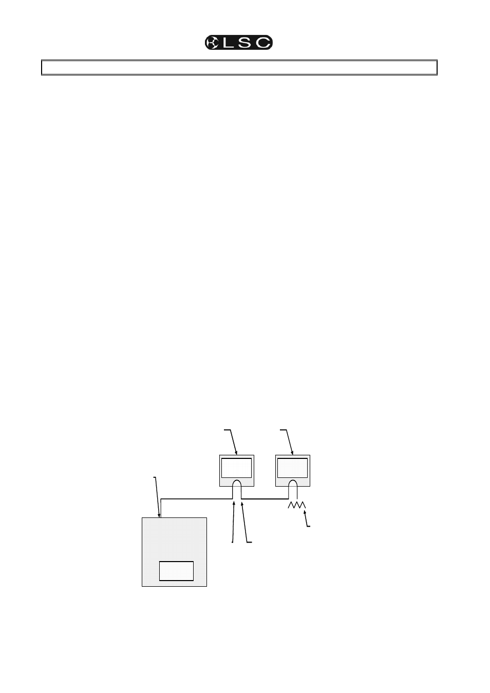
The following diagram illustrates a simple setup
utilising DMX512.
In this setup, the DMX output signal from the
maXim is fed to the DMX input of the first dimmer
rack. As the first dimmer in this rack is to be
controlled by DMX slot 1, the address switch is set
to slot 1. The DMX output connector of the first
rack is connected to the DMX input of the second
dimmer rack whose address switch is set to 13
because the first dimmer in this rack is to be
controlled by slot 13. Further dimmer racks are
connected in this daisy chain manner and their
addresses set accordingly. Address switches can
be set to any desired address. They do not have
to follow in numerical order. If a dimmer further
along the line is to be also controlled by say slot
13, then simply set its address switch to 13.
The end of the DMX line is terminated (120
Ω) to
prevent the signal reflecting back up the line and
causing possible errors. The termination might be
an external termination or it might be provided by
a switch on the equipment.
maXim S
DMX
OUT
DIMMERS
1 TO 12
DIMMERS
1 TO 12
DIMMERS
1 TO 12
TERMINATION
DIMMERS
13 TO 24
ADDRESS 1
ADDRESS 13
DMX 512
OUTPUT
DMX
IN
Simple DMX setup.