3 combined use of xlr and db25 cable sets, Combined use of xlr and db25 cable sets – Lynx Studio AES16 User Manual
Page 30
2BHardware Connections
3.4.3 Combined Use of XLR and DB25 Cable sets
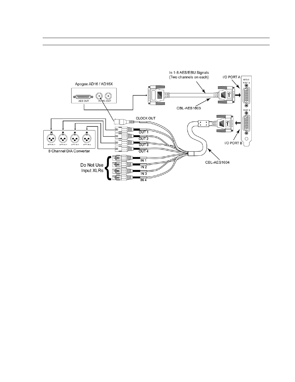
The figure below illustrates a “mixed mode” configuration, where the AES16 is connected to an Apogee AD16X
16-channel Analog-to-Digital converter and to some other 8-channel Digital-to-Analog converter. This represents a
unique situation, in that the AD16X will utilize all 16 available input channels while connected to a single I/O port
of the AES16, while only 8 output channels will be available to the D/A converter.
The AD16X is connected to the AES16 via our CBL-AES1603 cable, which is specifically designed to
accommodate the Apogee 16-channel converters through their D-Sub port. I/O Port B in this example is connected
to an 8-channel D/A converter using our CBL-AES1604 cable with standard XLR connections.
It is critical that the AES/EBU inputs on the CBL-AES1604 cable NOT be connected to any external device
since these inputs are connected electrically to inputs on I/O Port A. Doing so will degrade the quality of the
digital signal received on I/O Port A. Consequently, this configuration is limited to 16 input channels and 8
output channels, rather than the 16 in and 16 out which are possible with other cable set combinations.
ƽ
PLEASE NOTE: Since the CBL-AES1605 supports input and output signals through a single connector, it is not
advisable to use the CBL-AES1605 with the CBL-AES1603 at the same time.
In this example, the AES16 will function as the system clock master, with the Apogee AD16X and 8-channel D/A
converter acting as clock slaves. As shown, the word clock output available on the BNC connection of the CBL-
AES1604 cable is connected to the word clock input on the Apogee AD16X. The D/A converter can receive its
clock via the AES/EBU signal from the AES16, or from the word clock out of the AD16X. If the word clock is used,
a connection from the AD16X word clock out to the D/A word clock in is required.
I/O Configuration Jumper Settings
When using the CBL-AES1603 connected to an Apogee 16-channel converter, the associated I/O port on the AES16
must be set to 8 CHNL mode. For this example, set the jumper for I/O Port A to 8 CHNL mode. Confirm that the
I/O Port B jumper is in the factory default 4/4 CHNL mode. See Section 12.1 I/O Configuration Jumpers for more
information.
AES16 Clock Settings
To setup the AES16 as the system clock master, set Sample Clock Source in the Lynx Mixer Adapter window to
Internal.
External Equipment Clock Settings
AES16 User Manual
30