2 sample clock generator, 1 sample clock sources, 2 phase-lock loops and clock dividers – Lynx Studio AES16 User Manual
Page 42: Sample clock generator, Sample clock sources, Phase-lock loops and clock dividers, 4boperational overview
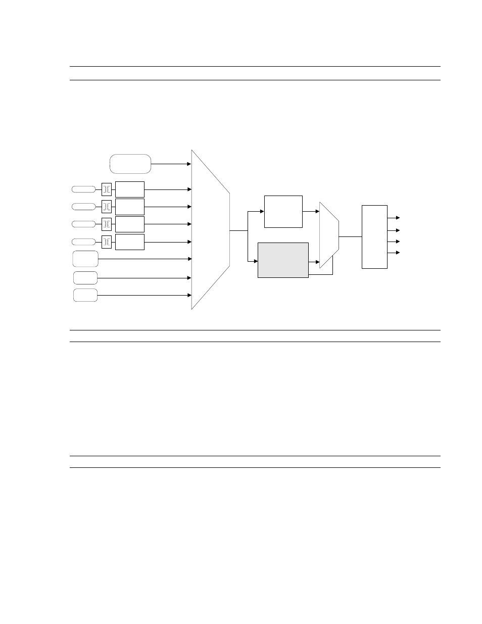
4BOperational Overview
5.2 Sample Clock Generator
The AES16 utilizes a master sample clock
generator to derive all clocks related to the
digital audio sampling rate. As shown in Figure
5 below, the sample clock generator provides a
selection of various clocks sources ands both a
wide range and SynchroLock phase-lock loop
(PLL).
AES-3
CLOCK
RECOVERY
IN 1
IN 2
IN 3
IN 4
AES-3
CLOCK
RECOVERY
AES-3
CLOCK
RECOVERY
AES-3
CLOCK
RECOVERY
LOW-JITTER
CRYSTAL
OSCILLATOR
DIGITAL IN 1
WORD CLOCK
DIGITAL IN 2
WORD CLOCK
DIGITAL IN 3
WORD CLOCK
DIGITAL IN 4
WORD CLOCK
EXTERNAL
CLOCK IN
(BNC)
HEADER
CLOCK IN
LSTREAM
PORT IN
SAMPLE CLOCK
SOURCE SELECT
WIDE RANGE
ANALOG PLL
SYNCHROLOCK PLL
PLL
SELECT
LOCKED
PLL
CLOCK
CLOCK
DIVIDERS
SYSTEM
CLOCKS
Figure 5: Sample Clock Generator
5.2.1 Sample Clock Sources
The sample clock generator can derive its
reference clock from both an internal and various
external sources. Only one source can be
selected at any given time. User control of the
sample clock source selector is provided on the
Adapter window of the Lynx Mixer application.
The available clocks sources are:
¾ On-board low-jitter oscillator (Internal)
¾ Digital In 1- 4: word clock recovered from
one of the first four AES-3 inputs
¾ External Clock In: signal from the CLOCK
IN BNC connector on the CBL-AES1604
break-out cable
¾ Header Clock In: signal from the board-
mounted header connector
¾ LStream Port In: word clock from an
LStream device connected to the LStream
header port
5.2.2 Phase-lock Loops and Clock Dividers
A two-stage phase-lock loop system is used to
generate a high-frequency PLL Clock while
attenuating jitter in the selected sample clock
source. Refer to the Section 5.3 SynchroLock
for a description of the operation of the PLL’s.
Clock dividers derive required system clocks
from the PLL clock.
AES16 User Manual
42