Part names and functions, Front panel, Rear panel – Marantz NA-11S1 User Manual
Page 48
45
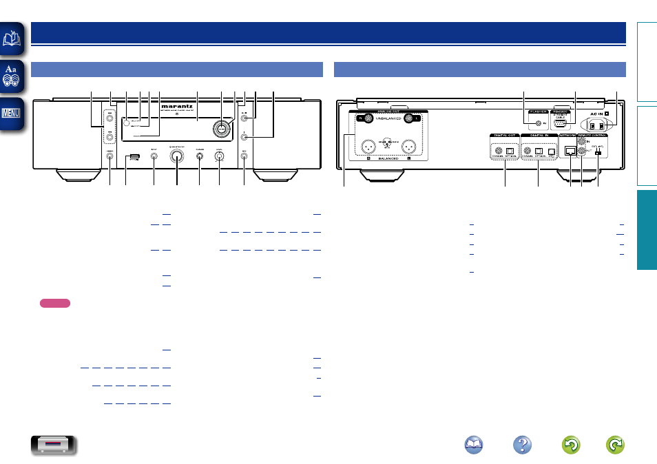
Part names and functions
For buttons not explained here, see the page indicated in parentheses ( ).
Front panel
q
w
e
r
t
y
u
i
o
Q0
Q1
Q2
Q6
Q7
Q3
Q5 Q4
Q8
Q0
q
DIMMER button ································· (
w
USB port ······································· (
Used to connect iPod or USB memory
devices.
e
INPUT button ······························· (
Selects the input source.
r
Power operation switch
(X ON/STANDBY) ····························· (
t
Headphones jack (PHONES) ············· (
Used to connect headphones.
NOTE
To prevent hearing loss, do not raise the
volume level excessively when using
headphones.
y
Headphone volume control knob
(LEVEL) ················································ (
u
Information button (INFO)
··················· (
i
Stop button (2)
························· (
o
Play/Pause button (1/3)
······························· (
Q0
Illumination lamp ······························ (
)
Q1
Cursor buttons (uio p)
············· (
,
,
,
,
,
,
,
,
)
Q2
ENTER button
············· (
,
,
,
,
,
,
,
,
)
Q3
Display
Displays play status, settings, etc.
Q4
STANDBY indicator ··························· (
)
Turns power to this unit on and off
(standby).
The STANDBY indicator changes as shown
below according to the status of the unit.
• Power on : Off
• Standby : Red
• “Network Control” – “On” : Orange
• iPod charge standby : Orange
Q5
Digital out off indicator
(DIGI. OUT OFF) ·································· (
)
Q6
DISPLAY OFF indicator ······················ (
)
Q7
Remote control sensor ························ (
)
Q8
Skip/Search buttons
(8, 9) ·········································· (
)
Rear panel
q
w
e
t
y
r
u
i
o
q
ANALOG OUT connectors
(UNBALANCED/BALANCED) ·············· (
w
DIGITAL OUT connectors ···················· (
e
DIGITAL IN connectors ························ (
r
NETWORK connector ·························· (
t
REMOTE CONTROL connectors
(IN/OUT) ··············································· (
y
External/Internal switch
(EXT./INT.) ············································ (
)
u
AC inlet (AC IN) ·································· (
)
i
RS-232C connector ······························ (
)
o
FLASHER IN jack (IN) ··························· (
)
Preparation
Operation
Information
Information