Step y.2 – set up the modem – Measurement Computing LogBook Series User Manual
Page 114
7-12 Using Modems and the Upload Scheduler
958896
LogBook User’s Manual
The configuration download cannot be accomplished via a serial port connection. This is
because once the modem configuration is downloaded to the PC-Card in the LogBook, the
LogBook will no longer be capable of serial port communication directly with the PC.
Reference Note:
If needed, refer to additional PC-card information in chapter 1 and in the LogView section of
this user’s manual.
8. Close LogView.
Step Y.2 – Set up the Modem
For many short-haul modems, it is necessary to configure one modem as the local modem (attached to the
PC) and one modem as the remote modem (attached to the LogBook). In some cases the setup is performed
by setting hardware switches on the devices and it others it is performed via software commands.
Some modems require the user to setup the serial parameters; e.g., baud rate, stop bits, and
parity. Make sure these match the setup of the communications parameters that are
selected in the LogBook Configuration control panel applet.
For information on how to perform these setup operations, refer to the instructions supplied with your
modems.
Step Y.3 – Physically Connect the LogBook to the Modem
1. If your LogBook has the LBK/COM/422/485 option installed, verify that the option is set for RS-232
communication. The option is discussed in chapter 5. (See following note).
If you are using the LBK/COM/422/485 communications option you will need to
ensure that the option board is positioned on LogBook’s internal slot “CN8” such
that the RS-232 communication mode is enabled. If your LogBook has the
LBK/COM/422/485 option and you are uncertain about the communication mode,
refer to chapter 5, LBK and other non-DBK options. The chapter section entitled
LBK/COM/422/485
explains how to set the communications option for RS-232.
2. Connect the modem to the LogBook’s 9-pin Serial COM port. Refer to your modem instruction
manual for connection issues, recommended configurations, and cable types.
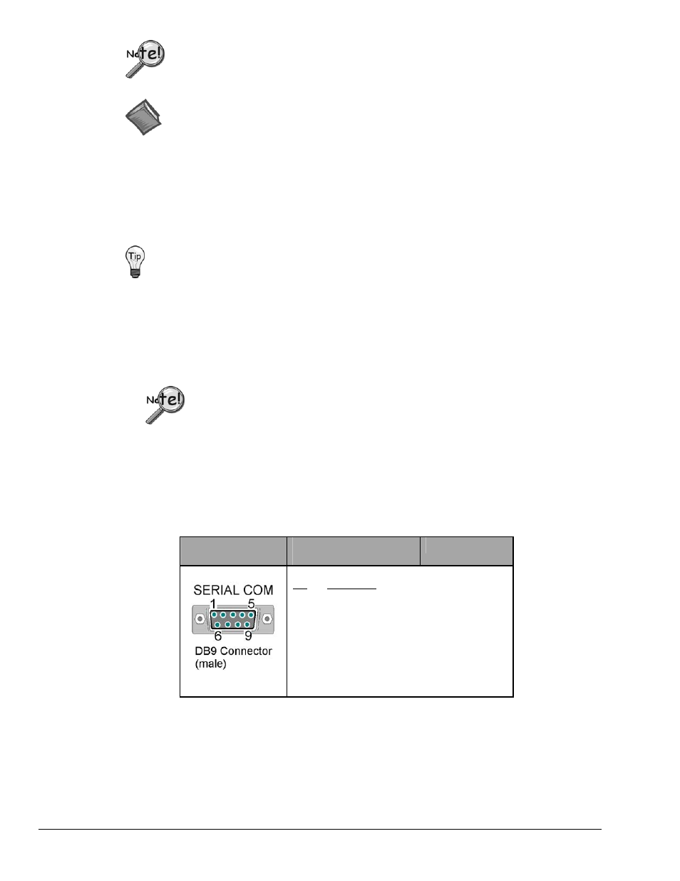
9-Pin Connector
On LogBook
LogBook’s Serial COM
Pinout
Modem Signals
Pin
1
2
3
4
5
6
7
8
9
Description
Not Used
RxD ------- connects to --- TxD
TxD --------connects to --- RxD
Not Used
Common ---connects to -- Common
Not Used
RTS ---------connects to ---CTS
CTS ---------connects to --- RTS
Not Used
Modem Connection to LogBook’s Serial COM Port
3. Turn power on to the LogBook and the modem.