Caution, Hardware configuration – Measurement Computing LogBook Series User Manual
Page 29
QS300
-4
LogBook/300 Quick Start Guide
2. Connect the LogBook/300 to the DBK cards and modules. Most of the analog DBKs connect to P1
on the rear panel; the digital DBKs generally connect to P2.
Reference Note:
For DBK card related information, refer to the DBK Options Manual PDF. The document is
included on the Data Acquisition CD and is also available on our web-site.
Note: The CA-37-x cable can daisy-chain several DBKs including the DBK41, which has a built-in
P1 bus connection for 10 DBK cards. The x in the cable part number refers to the number of
devices that can be connected to a device, for example: a CA-37-1 cable has two DB-37
connectors, one for connecting to the LogBook and another for connecting the card or
module. Pinouts for P1, P2, and P3 are included in the System Expansion chapter.
CAUTION
For analog signal inputs via P1, do not exceed -35 VDC or +45 VDC.
Exceeding these limits could result in equipment damage.
3. Connect DBK(s) to transducer(s). Follow instructions for the specific DBK(s) as described in the
DBK Option Cards & Modules User’s Manual, as well as instructions for the applicable transducers.
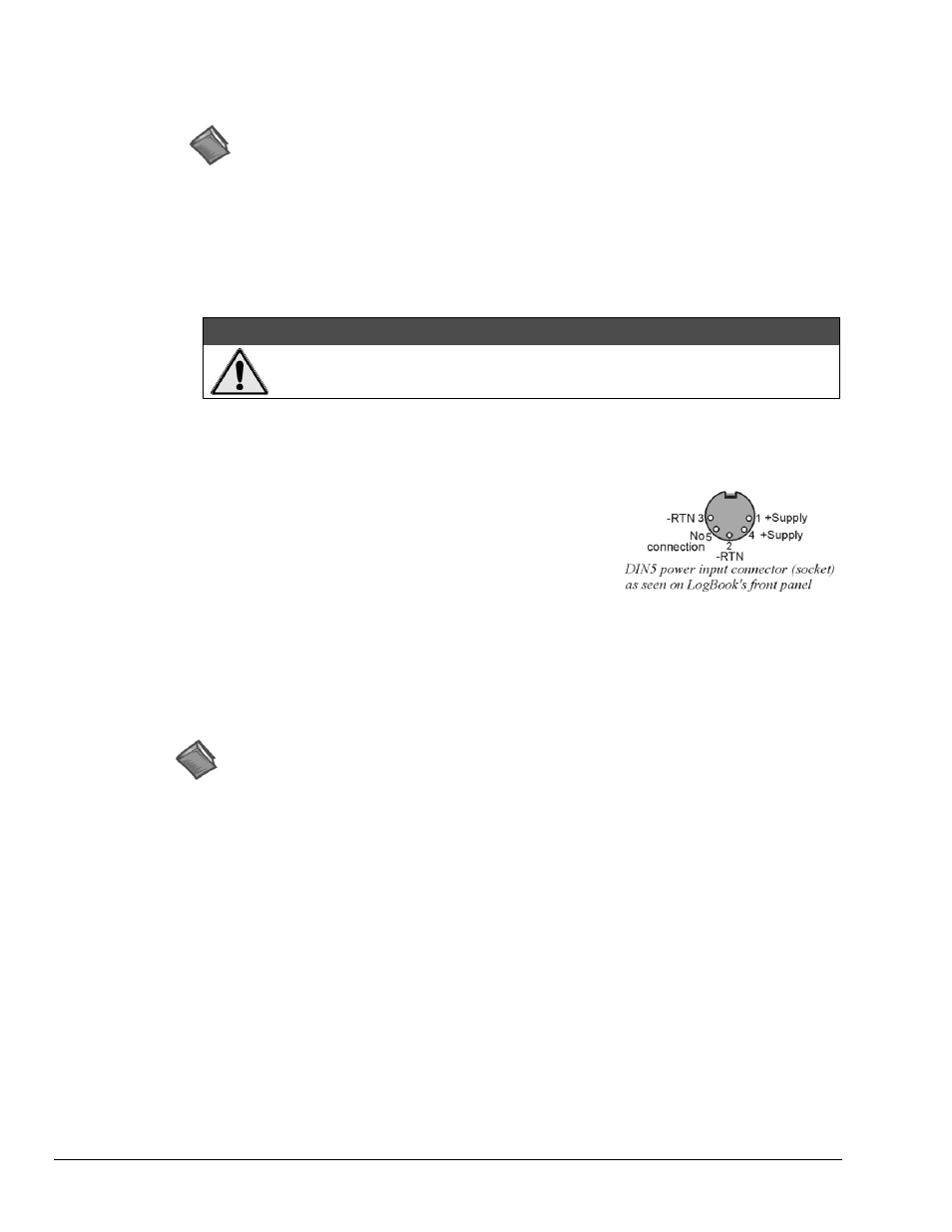
4. Connect the LogBook/300 to a suitable power source such as the
included AC-to-DC adapter or the optional DBK34A. DC
power sources such as a car batteries must supply 10 to 45 VDC
and use the correct DIN5 pinout (see figure). A locking DIN5
connector assures a secure power connection for applications
subject to vibration or thermal stress.
5. Optional - Just one cable connects between the LBK1
(via RJ-11 connector) and the LogBook/300 (via a DB9 connector). The standard cable is 6 feet
long. An optional 25 foot cable is available. See chapter 5 of the LogBook User’s Manual PDF for
details regarding the installation of LBK1.
Hardware Configuration
Reference Note:
Refer to the device-specific sections of the LBK Options chapter of the user’s manual and to
the DBK Options Manual PDFs for information regarding these devices. Note that certain
DBK options require manual configuration.
LogBook/300's top cover does not need to be removed, except to add or remove an LBK option, or to
replace the fuse.
Most LogBook/300 configuration is done via software as described in the LogBook/300 Device
Configuration section of this document (page
QS300
-5). LogBook/300 configuration does not require the
setting of jumpers or switches, unless the RS-485 communication option is being used.