Dbk identification tables, Analog output dbks, Digital i/o control dbks – Measurement Computing LogBook Series User Manual
Page 63
Daq Systems
967794
DBK Basics, pg. 9
DBK Identification Tables
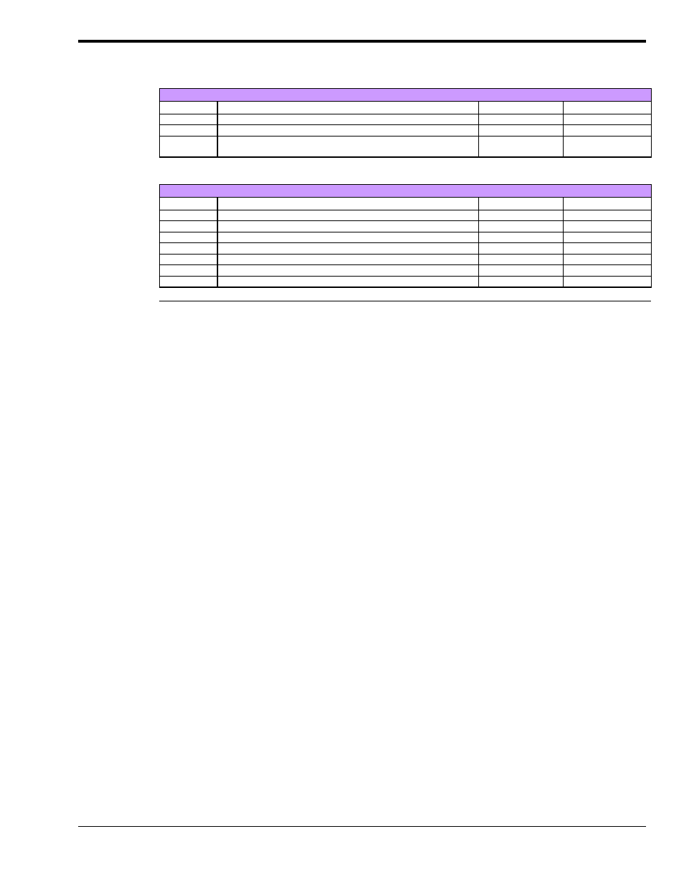
Analog Output DBKs
Analog Output
Product
Name/Description
I/O
Connects To:
DBK2
Voltage Output Card
4 channels
P1
DBK5
Current Output Card
4 channels
P1
DBK46
Analog Output Card option for designated devices
4 channels
Internal
PC Board
Digital I/O Control DBKs
Digital I/O / Control
Product
Name/Description
I/O
Connects To:
DBK20
General-Purpose Digital I/O Card (Screw Terminals)
48 channels
P2
DBK21
General-Purpose Digital I/O Card (DB37 Connectors)
48 channels
P2
DBK23
Optically Isolated Digital-Input Module
24 channels
P2
DBK24
Optically Isolated Digital-Output Module
24 channels
P2
DBK25
Relay Output Card
8 channels
P2
DBK208
Carrier board for Opto-22 Compatible SSR Digital Modules.
16 Channels
P2 or P4
DBK210
Carrier Board for Grayhill 70M-Series Mini-Modules
32 Channels
P2 or P4, P1 exp.
Notes
o
P1, P2, and P3 DB37 connectors do not exist on the DaqBoard/2000 Series boards or /2000c
Series boards, but are obtained by using P4 adapters (DBK200 series boards).
o
For DaqBoard/2000 Series devices, unless otherwise noted, the internal clocks should be set to
100 kHz when used with any of the following DBK options: DBK12, DBK13, DBK15, DBK19,
DBK52, DBK53, and DBK54. See specific DBK section for details.
o
DaqBoard/500 Series boards do not support DBK options.
o
DaqBoard/1000 Series boards do not support DBK options.
o
DaqBook/2000 “AEX” devices have P1, P2, and P3 connectors and, in addition a P4 connector.