Lbk2, four channel digital-to-analog output option, Warning, Caution – Measurement Computing LogBook Series User Manual
Page 85
LogBook User’s Manual
919495
LBK and other non-DBK Options 5-9
LBK2, Four Channel Digital-to-Analog Output Option
The optional D/A output board contains four 16-bit, voltage-output, digital-to-analog converters with a
maximum update rate of 100 kHz per channel. The board is intended for waveform generation, UUT
stimulus, and signal feedback. Each converter has a fixed, full-scale output of ±10 VDC. The board’s
operation must be programmed through LogView.
The D/A output board has been designed for operation into loads of >2000
Ω resistance with <100 pF of
parallel capacitance. The D/A board is stable with all capacitive loads; however, increased capacitive
loading will result in longer settling times.
Name: Analog Output Board
Output Voltage Range: ±10 VDC.
Voltage Resolution: (1 LSB): 305
µV
Offset Error: ±0.0045 V
Full Scale Error: ±0.01%
Settling Time For 20 Volt Step: <10
µs
The D/A output board is an edge-card design and plugs into a 30-pin SIMM socket.
If not factory-installed, the D/A board can be easily installed by the user as follows:
WARNING
Electric shock hazard. Turn off power to all system-connected devices prior to
connecting or disconnecting cables, or setting hardware configurations. Failure to
do so could result in electric shock or death, and equipment damage, even under
low-voltage conditions.
CAUTION
Perform the following procedure using ESD tools, containers, and procedures. One
or more related components are sensitive to damage from electrostatic discharge.
1. Turn off system power.
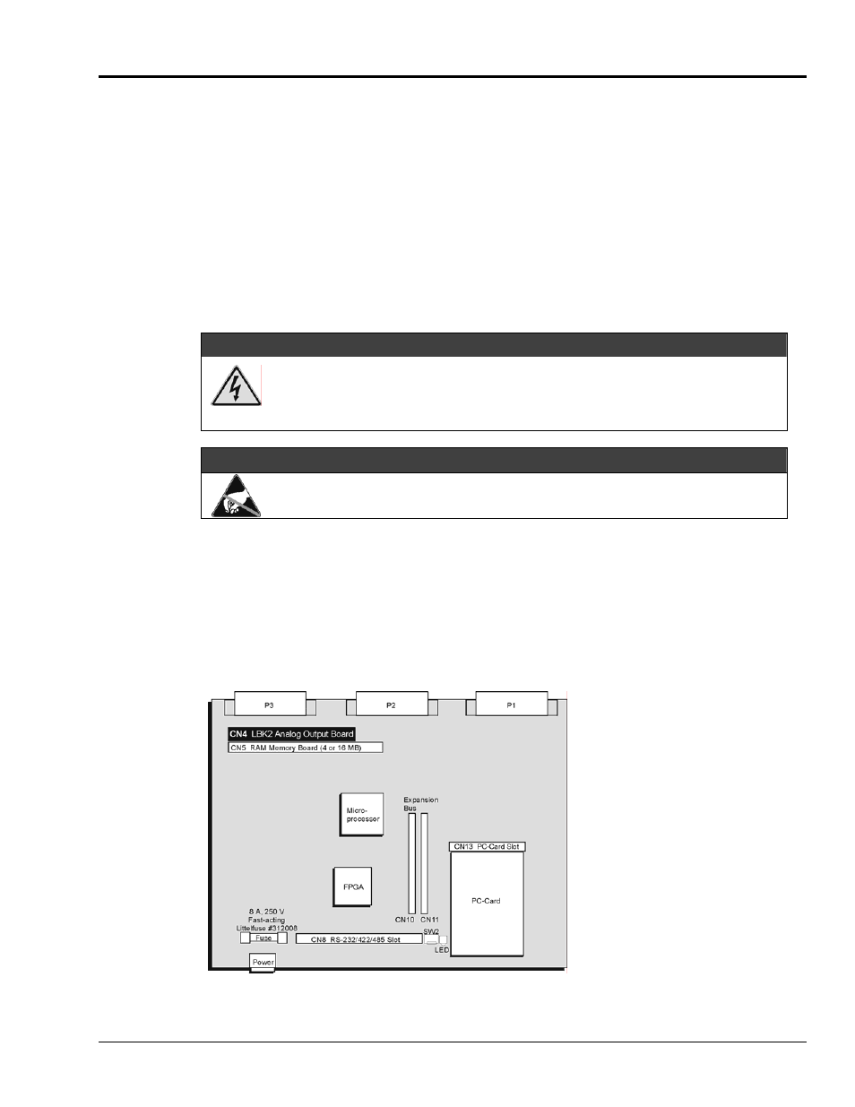
2. Remove the LogBook’s top cover and locate CN4 (a 30-pin SIMM socket), see following figure.
3. To gain access to CN4, first remove the RAM memory board from CN5.
4. Using ESD precautions, remove the bypass board from CN4.
5. Using ESD precautions, insert the LBK2 analog output board into CN4. Note that the board and
socket are keyed to mate one-way-only, and will lock together when properly mated.
6. Using ESD precautions, replace the RAM memory board into CN5.
7. Replace the top cover and screws.
8. Turn on system power.
Notes:
CN4 and CN5 slots each have
two release clips that must be
depressed in order to release
cards.
The LBK2 Analog Output
Board inserts into the CN4 slot
on LogBook’s Motherboard.
LogBook Motherboard, CN4 Location Reference