Typical mh installation – Nortec MH Series User Manual
Page 15
Installation | 12
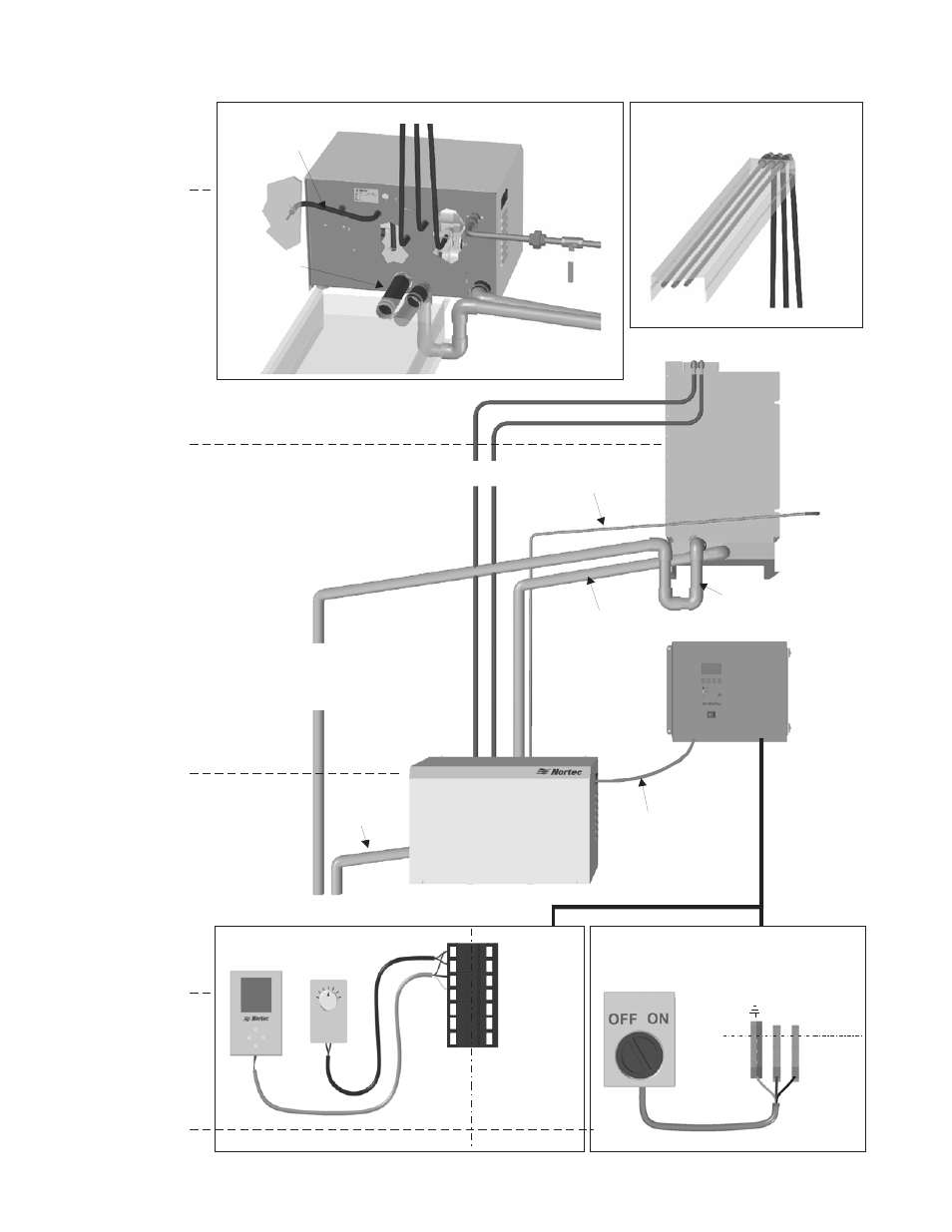
Typical MH Installation
Figure 10: Typical MH Installation
L1
N
Gr
oun
d
Dedicated
Circuit Breaker
or Disconnect
MH
EXT
Connect spray bar lines
to spray bar.
Spray Bar Lines
Water Supply
30-80 psig
Drain and
overflow lines
Pressure
Equalization
Line
Drain pan
to hydraulic
unit
Spray Bar Lines
Pressure
Equalization Line*
Drain Pan to
Hydraulic Unit*
P-Trap
Spray Bar Lines
Connect to drain pan
overflow on Reflow or
to drain on Flow.
Control box to
hydraulic unit
wiring
(13-17 wires)
Reflow and Flow only
Control Box
Duct Module
Hydraulic Unit
Hydraulic
unit drain*
Note: MHTC Reflow show.
* = only required on
Reflow model.
E
X
T
M
H
1- 24 VAC
2 - On/Off Loop
3 - Ground
4 - Control Signal
5 - N/A
6 - +5 VDC
7 - Ground
On/Off
Controls
Modulation
Control
c
l
y
Plumbing
Pg 22
Duct Module
Assembly
Pg 15
Hydraulic
Unit
Location
Pg 14
Controls
Pg 27
Electrical
Pg 25