Transducer control wiring – Nortec MH Series User Manual
Page 33
Installation | 30
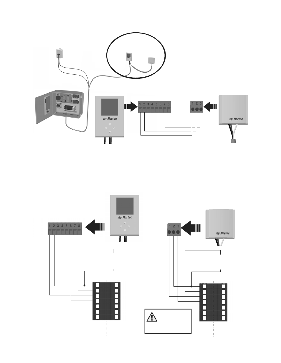
Figure 30: Remote Sensor to Humidistat Wiring
Transducer Control Wiring
Figure 31: Transducer Wiring
Air Proving
Switch
Digital On/Off
Humidistat
Duct Sensor
1 -
G
rou
nd
2
- 2
4 VA
C
7 -
A
nalog
In
1 -
Grou
nd
2 -
24 V
A
C
3 -
An
alog
Out
Wire remote sensor to digital display as shown below,
Wire digital display to MHTC as shown above.
2520266 - Digital Duct Humidistat Package
1
2
3
4
5
6
7
E
X
T
M
H
1- 24 VAC
2 - On/Off Loop
3 - Ground
4 - Control Signal
5 - N/A
6 - +5 VDC
7 - Ground
1
2
3
4
5
6
7
E
X
T
M
H
1- 24 VAC
2 - On/Off Loop
3 - Ground
4 - Control Signal
5 - N/A
6 - +5 VDC
7 - Ground
1
2
3
4
5
6
7
E
X
T
M
H
1- 24 VAC
2 - On/Off Loop
3 - Ground
4 - Control Signal
5 - N/A
6 - +5 VDC
7 - Ground
1
2
3
4
5
6
7
E
X
T
M
H
1- 24 VAC
2 - On/Off Loop
3 - Ground
4 - Control Signal
5 - N/A
6 - +5 VDC
7 - Ground
1
-
G
roun
d
2 -
2
4 V
A
C
6 -
A
nal
og O
ut
1509858 - 2-10V Wall Humidity
Transducer
Insert On/Off
controls or jumper
between 1 and 2
1 -
G
rou
nd
2
- 2
4 VAC
3
- A
n
al
o
g O
ut
Insert On/Off
controls or jumper
between 1 and 2
1509857 - 2-10V Duct Humidity
Transducer
Connect 24 VA C,
terminal 1 of
MHTC to
terminal 2
of controllers