Modulating control wiring – Nortec MH Series User Manual
Page 32
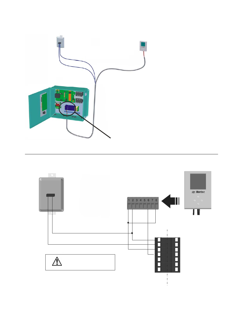
29 | Installation
Modulating Control Wiring
Figure 28: Modulating Controls
Figure 29: Digital Modulating Humidistat
1 -
G
rou
n
d
2
- 2
4
V
A
C
4 -
A
na
lo
g O
u
t
8 -
T
em
per
at
ur
e
Air Proving Switch
Wire to make when
sensing air flow
Connect 24 VA C,
terminal 1 of MHTC to
terminal 2 of controllers.
N/
O
Co
m
Modulating Humidistat
1510142 - Digital Wall Humidistat or
2520266 - Digital Duct Humidistat Package*
M
H
E
X
T
1- 24 VAC
2 - On/Off Loop
3 - Ground
4 - Control Signal
5 - N/A
6 - +5 VDC
7 - Ground
1
2
3
4
5
6
7
* See below for wiring sensor to digital display
Humidifier Terminal Strip
Air Proving
Switch
Modulating Humidistat,
1510142 - Digital Wall Humidistat or
2520266 - Digital Duct Humidistat Package.
Note: 1
2
3
See MHTC configuration for information
on configuring the MHTC to operate on a
modulation signal.
Install On/Off controls or jumper between
terminal 1 and 2 of MHTC in order to run.
Terminal 1 is 24VAC Hot, turn unit off to
avoid shorting while wiring.