Remote relay board wiring – Nortec MH Series User Manual
Page 36
33 | Installation
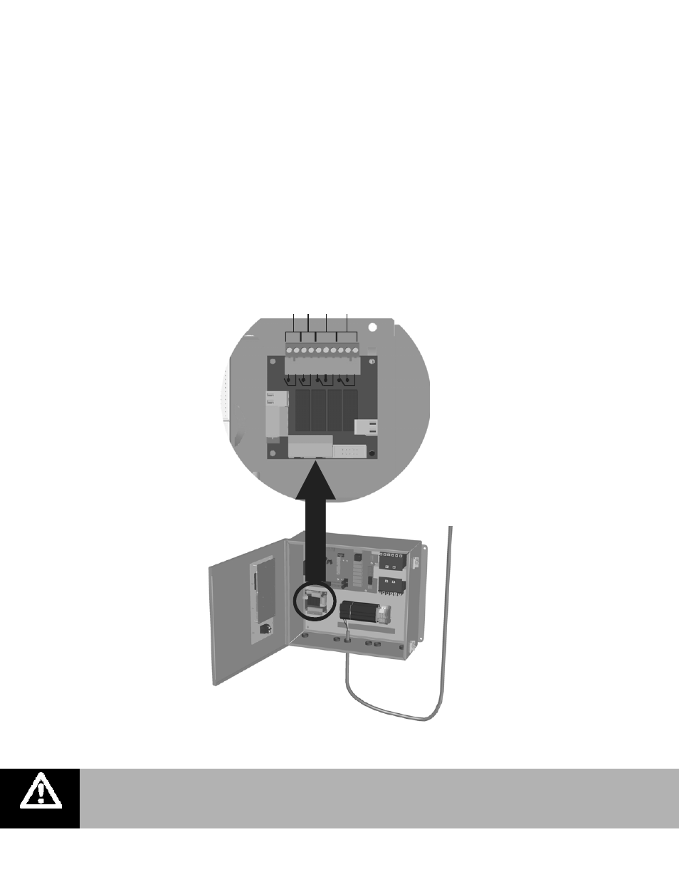
Remote Relay Board Wiring
The MHTC (not MHB) remote relay board includes 4 relays that can provide remote status
indication. The remote relay board is located as shown in Figure 36: Remote Relay Board
Wiring. The PCB with the relays includes markings which indicate the function of each terminal
on the board. The relays indicate the following status;
1 Unit On – The normally open relay is closed when the humidifier has power and the On/Off
switch is set to on.
2 Steam – The normally open relay is closed when the control board activates at least one
staging valve and water is being evaporated from the evaporative media.
3 Service – The relay can be wired to open (NC) or close (NO) when a warning is displayed on
the MHTC display and the yellow service LED is illuminated.
4 Error – The relay can be wired to open (NC) or close (NO) when a fault is detected by the
MHTC controls.
Figure 36: Remote Relay Board Wiring
S
team
U
n
it
O
N
Erro
r
Se
rv
ic
e
NO
CO
M
NO
CO
M
NO
CO
M
NC
NO
CO
M
NC
Note:
MHTC units with Nortec Links XPS have the Links XPS board installed in place of the
remote relay board.