Duct module assembly and installation – Nortec MH Series User Manual
Page 18
15 | Installation
Duct Module Assembly and Installation
Usually, the design and dimensioning of the ventilation duct/air handler as well as the location
of the Nortec MH inside the duct are determined, recorded and specified when planning the
entire system. The following 8 steps provide a guide for assembling the duct unit. Assembly
should only be carried out by qualified personnel familiar with duct and air handler construction.
The assembly shown shows the drain pan being mounted and fastened to the base of the duct.
It may be necessary to raise the drain pan in the duct to achieve proper P-Trap height on the
drain or overflow. Ensure proper height is available for a P-Trap equal to 6 in (15 cm) or duct
static pressure + 2 in whichever is greater.
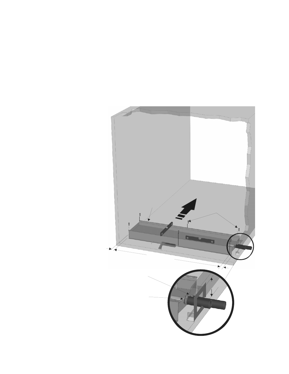
Step 1 - Drain Pan
Figure 13: Drain Pan Installation
Air
Flow
Cutout
Duct
Install hose
cuffs on both
tank drain
connections.
1/4 x 3/4 Self
tapping screws (6x)
Drain Pan
Equal gaps
Overflow Outlet
Drain Pan Drain
Outlet
Duct or air handler
plenum
Install drain pan
ensuring it is level.
Orient the drain pan
with respect to air flow
so that the overflow
outlet (higher) is
upstream of the drain
pan drain outlet.
Leave an equal gap on
both sides of the drain
pan.
Caulk around screws
and any other openings
used to fasten the
drain pan to the base
of the duct.
Make a cutout in the
side of the duct for
drain connections and
install hose cuffs of
sufficient length to
connect to hydraulic
unit or drains.
Seal duct wall around
hose cuffs with cover
plate (by others).