Using the external clock function, Appendix i – 8530 board level option, 8530 board level connection information – Quantum Composers 9530 Series User Manual
Page 61: Oard, Evel, Verview, Igital, Ontrol, Onnection, Nformation
9530/8530 Manual Version 4.8
Page 61
*Note: These specifications are preliminary and subject to change.
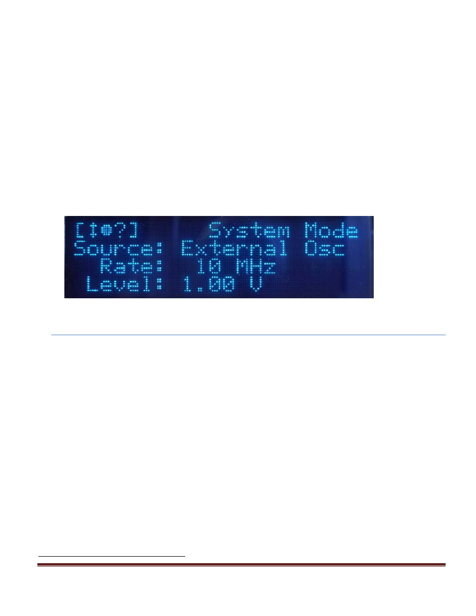
Using the external clock function:
Enter the system menu pages and find the clock menu page. Enter the clock source
menu by pressing the page button until the clock source page is reached.
Select the source to External Osc or External PLL.
Adjust the threshold level to trigger between 10% and 30% of the High-Z input
amplitude of the external clock source. For example when clock source is connected
to a 1MΩ input of an oscilloscope.
Adjust the rate to match the frequency of the external clock source.
A
“?” will appear if the system does not lock onto the external clock source when in
External PLL mode. Possible causes are:
o
Threshold level not adjusted correctly.
o
External clock source not present.
o
External clock has excessive jitter.
o
Amplitude of external clock is changing.
Figure 1: System Display Screen Shot
16.
Appendix I
–
8530 Board Level Option
8530 Board Level Connection Information
8530 Board Level Overview
The 8530 is a board level option based on the 9530 series pulse generator. The
specifications, communications, and overall functionality of the 8530 are the same as
described for the 9530 series. The 8530 is available with either 4 or 8 independent outputs
that can be used for synchronizing multiple events. With the 8530 all communications will
take place through USB, Ethernet, or RS-232 as there is no display or keypad for
interactions. The guide for standard SCIP communications with the 8530 unit can be found
above in the 9530 standard manual. As with the 9530, the 8530 is capable of generating
multiple pulses for all applications; but additional setup is required before even basic
pulsing may begin.
Digital Control Board Connection Information
*Note: The Power Input and Power Switch Connector are required connections for the 8530
module to function.
Power Input Connector (J2 - DC In)