Igital, Utput, Oard – Quantum Composers 9530 Series User Manual
Page 65: Onnection, Nformation, Ounting, Digital output board connection information, Mounting information
9530/8530 Manual Version 4.8
Page 65
Digital Output Board Connection Information
Digital Control Board Input (J1 or J2)
The Output Board must be connected to the Digital Control Board via one of the two
surface mounted Mini Card Edge Connectors
*Note: All other connections, besides to the Digital Control Board, will be made to the Output Board
with male BNC connectors.
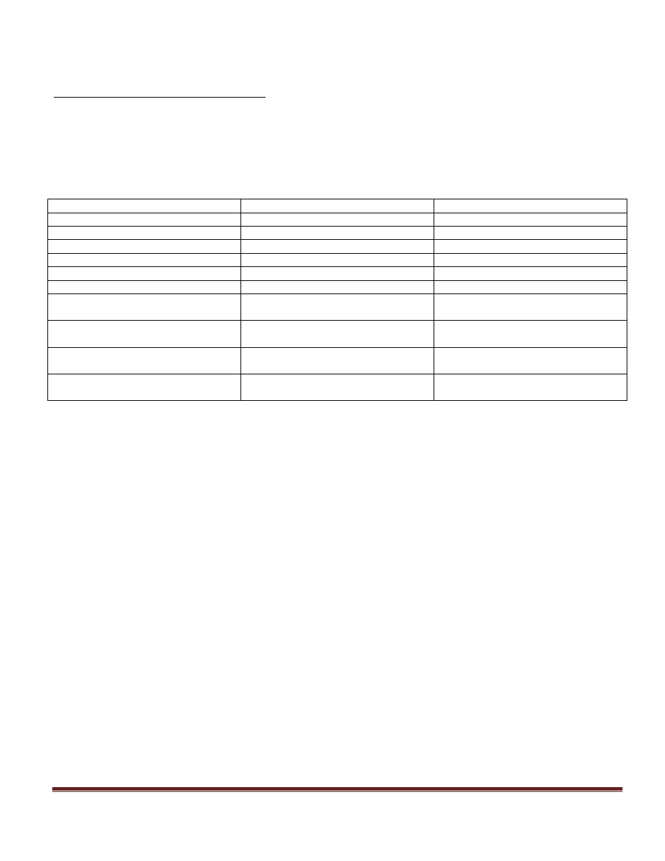
Connector Name:
Connector Designator:
Connector Function:
Gate
J6
External Gate Input
Trigger
J7
External Trigger Input
A
J4A
Channel A Output
B
J5A
Channel B Output
C
J4B
Channel C Output
D
J5B
Channel D Output
E (will only be present on 8 channel
models)
J2A
Channel E Output
F (will only be present on 8 channel
models)
J3A
Channel F Output
G (will only be present on 8 channel
models)
J2B
Channel G Output
H (will only be present on 8 channel
models)
J3B
Channel H Output
Mounting Information
There are 5 X 6-23 screw holes that should be used to mount the Control Board.
There are 7 X 6-32 screw holes that should be use to mount the Output Board.
*Note: Each of these mounting holes are connected to Ground
*Note: 4 of the 7 holes on the output board are use to mount the optional 4 channel expansion
board and will come with custom made M-F standoffs if the 8538 is ordered.