Hardware description, Front panel, Hardware description -2 – Quintum Technologies Call Routing Server User Manual
Page 13: Front panel -2
2-2
P/N 480-0028-00-00
Chapter 2: Hardware Installation
Hardware description
Front Panel
The Tenor Call Routing Server is a stackable/rack mountable device which connects to a PC console and
Ethernet network.
The unit’s front panel includes connection jacks, LEDs, etc.
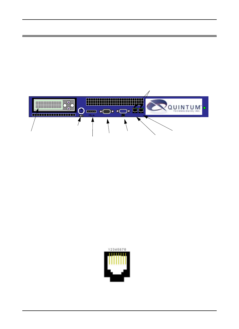
Figure 2-1 Routing Server - front panel
LCD Screen. This screen is used for assigning an IP address to a Call Routing Server and various other status
functions. The LCD has four buttons: Up arrow, Down arrow, escape, and enter. The Up and Down arrows
enable you to enter each number of the IP address. Pressing ENTER confirms the numbers in the database;
pressing ESC will undo the last action. See Chapter 3: Using the LCD front panel/Setting IP address for more
information.
PS2 Keyboard. Not used.
USB Port. Not used.
Console Port. Not used.
VGA Port. Not used.
LAN 1 port. Ethernet port provides an RJ-45 jack for individual connection to a 10/100 Ethernet LAN switch
or hub via RJ-45 cable. The Ethernet port enables connection between an Ethernet hub/switch and the Call
Routing Server. This connection is required for installation.
Figure 2-1 10/100 Ethernet Port Pin Order
LAN 1 LAN 2
10101
ESC
ENTER
LCD Screen
PS2/Keyboard
VGA Port
Console
Port
LAN port1
USB port
LAN Port LEDs
LAN Port 2