Nim 2000 network interface module, Nim 2000 network interface module -6 – Verilink NCM 2000 (880-502623-001) Product Manual User Manual
Page 16
NCM Overview
1-6
Verilink NCM 2000
Front Panel LEDs
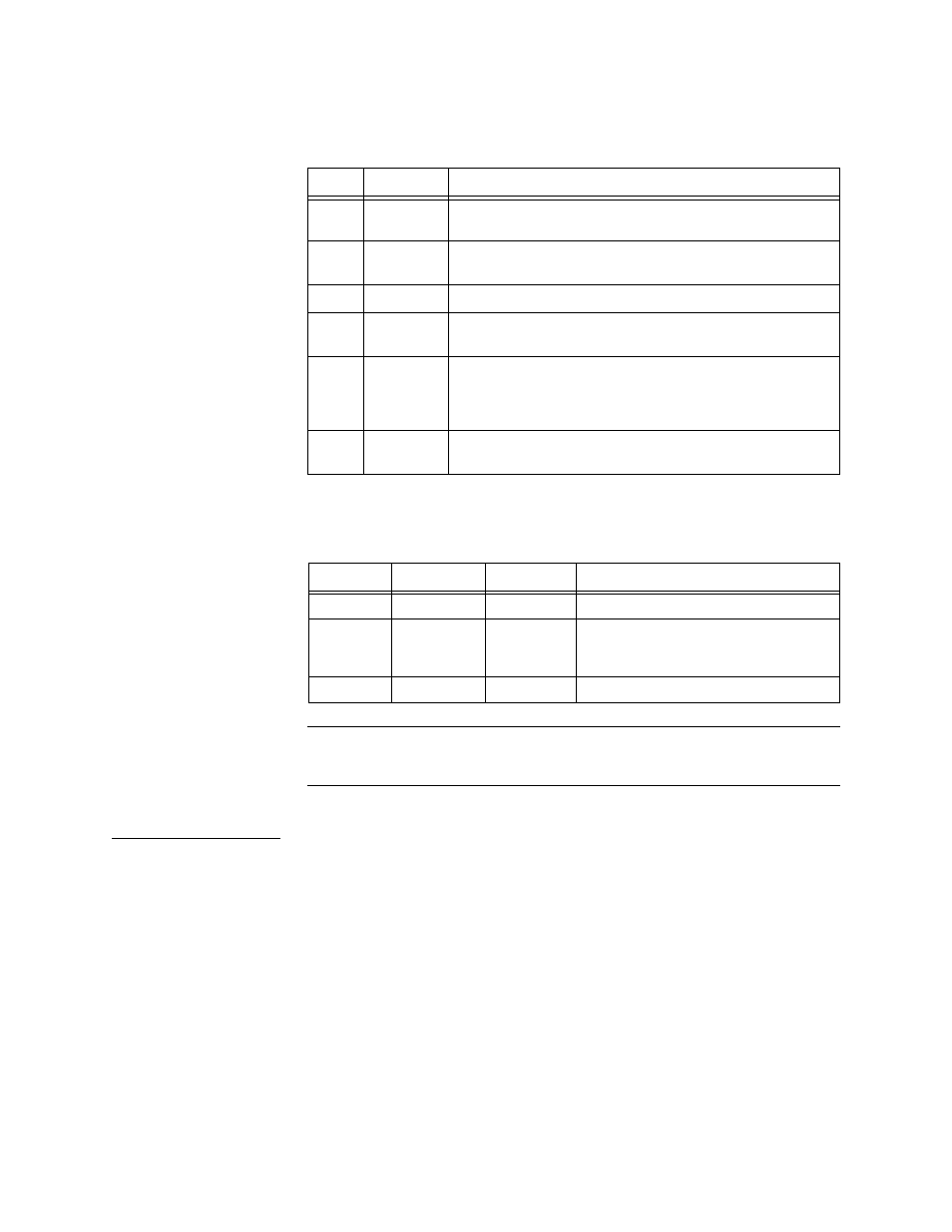
The NCM front panel provides six tri-color status LEDs:
Table 1-1 NCM 2000 Front Panel LEDs
Management Ports
The NCM 2000 has three front panel management ports.
Table 1-2 NCM 2000 Front Panel Connectors
NOTE: For operator convenience, the PRI and EXT ports are redundant with
the same connectors on the connector interface module (NIM 2000),
which is accessible at the rear of the shelf.
NIM 2000
Network
Interface Module
The NIM 2000 (Network Interface Module 2000) is mounted on the
rear of the shelf, behind the NCM. The NIM 2000 ports are listed in
below:
LED
Name
States
TX
Transmit Flashes green whenever this NCM transmits a packet to
the Ethernet.
RX
Receive
Flashes green whenever this NCM receives a packet from
the Ethernet.
COL
Collision
Flashes amber whenever there is an Ethernet collision.
ACT
Active
Steady green if the NCM is the active NCM, flashing
green to off if the NCM is the standby NCM.
ALM
Alarm
Steady red if there is a Major or Critical alarm on any of
the modules in the node. Glows steady amber if a power
supply is missing. Green means no alarm. It is off on a
standby NCM.
SYS
System
Steady green, indicating the module is powered up
normally, having passed the power-up self-test.
Port
Connector
Interface
Use
L
OCAL
RJ-11
RS-232
ASCII terminal operations
PRI
RJ-45
RS-232
ACP bus connection to Node
Manager, or SLIP port if SLIP is being
used
EXT
RJ-45
RS-232
Daisy-chain to next ACP shelf