Wire gauges and tightening torques, 3 electrical installation – Yaskawa A1000 6-Phase/12-Pulse Input User Manual
Page 23
u
Wire Gauges and Tightening Torques
Use the tables in this section to select the appropriate wires and crimp terminals.
Gauges listed in the tables are for use in the United States.
Note:
1. Wire gauge recommendations based on drive continuous current ratings (ND) using 75 °C 600 Vac vinyl-sheathed wire assuming ambient
temperature within 40 °C and wiring distance shorter than 100 m.
2. Terminals
⊕3 and ⊖ are for connecting optional power devices. Use caution to connect only approved devices to the correct terminal(s).
• Consider the amount of voltage drop when selecting wire gauges. Increase the wire gauge when the voltage drop is greater
than 2% of motor rated voltage. Ensure the wire gauge is suitable for the terminal block. Use the following formula to
calculate the amount of voltage drop:
Line drop voltage (V) = 3 × wire resistance (Ω/km) × wire length (m) × current (A) × 10
-3
• Refer to CDBR manual TOBP C720600 00/TOBP C720600 01 for dynamic braking wire gauges.
• Use terminals
⊕3 and ⊖ when connecting a CDBR dynamic braking unit.
• Do not connect a regenerative converter or a regenerative unit to the 6-Phase/12-Pulse drive.
•
Refer to UL Standards on page 84
for information on UL compliance.
Yaskawa recommends using closed-loop crimp terminals on all drive models. UL/cUL approval requires the use of closed-
loop crimp terminals when wiring the drive main circuit terminals. Use only the tools recommended by the terminal
manufacturer for crimping.
Refer to Closed-Loop Crimp Terminal Size on page 86
for closed-loop crimp terminal
recommendations.
The wire gauges listed in
are Yaskawa recommendations and are based on the 6-Phase input current ratings specified
. Refer to local codes for proper wire gauge selections.
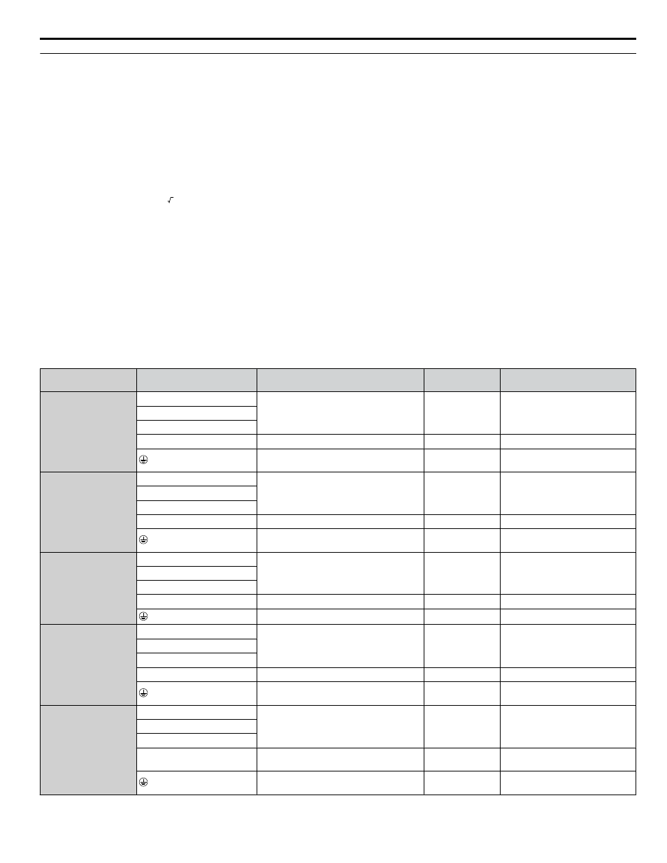
Table 5 Wire Gauge and Torque Specifications
Drive Model
Terminal
Wire Range
AWG, kcmil
Screw
Size
Tightening Torque
N·m (lb.in.)
4T0058o
R/L1, S/L2, T/L3
10 to 1/0 (5.3 to 53.5)
M8
9 to 11
(79.7 to 97.4)
R1/L11, S1/L21, T1/L31
U/T1, V/T2, W/T3
B1, B2
22 to 10 (0.3 to 5.3)
M4
1.2 (10.6)
Refer to applicable codes for wire size
M8
9 to 11
(79.7 to 97.4)
4T0072o
R/L1, S/L2, T/L3
10 to 3/0 (5.3 to 85.0)
M8
9 to 11
(79.7 to 97.4)
R1/L11, S1/L21, T1/L31
U/T1, V/T2, W/T3
B1, B2
22 to 10 (0.3 to 5.3)
M4
1.2 (10.6)
Refer to applicable codes for wire size
M8
9 to 11
(79.7 to 97.4)
4T0088o
4T0103o
R/L1, S/L2, T/L3
6 to 250 (13.3 to 127)
M8
9 to 11 (79.7 to 97.4)
R1/L11, S1/L21, T1/L31
U/T1, V/T2, W/T3
⊖, ⊕3
22 to 1/0 (0.3 to 53.5)
M6
2.5 to 3.0 (22.1 to 26.6)
Refer to applicable codes for wire size
M8
9 to 11 (79.7 to 97.4)
4T0139o
4T0165o
R/L1, S/L2, T/L3
22 to 1/0 (0.3 to 53.5)
M6
2.5 to 3.0
(22 to 1/0)
R1/L11, S1/L21, T1/L31
⊖, ⊕3
U/T1, V/T2, W/T3
6 to 250 (13.3 to 127)
M8
15.0 (132.8)
Refer to applicable codes for wire size
M10
18 to 23
(159.3 to 203.6)
4T0208o
R/L1, S/L2, T/L3
Refer to applicable codes for wire size
M10
18 to 23
(159.3 to 203.6)
R1/L11, S1/L21, T1/L31
U/T1, V/T2, W/T3
⊖, ⊕3
22 to 1/0 (0.3 to 53.5)
M6
2.5 to 3.0
(22.1 to 26.6)
Refer to applicable codes for wire size
M10
18 to 23
(159.3 to 203.6)
3 Electrical Installation
YASKAWA TOEP YAIA1U 02A YASKAWA AC Drive – A1000 6-Phase/12-Pulse Input Installation Manual
23