Yaskawa A1000 6-Phase/12-Pulse Input User Manual
Page 33
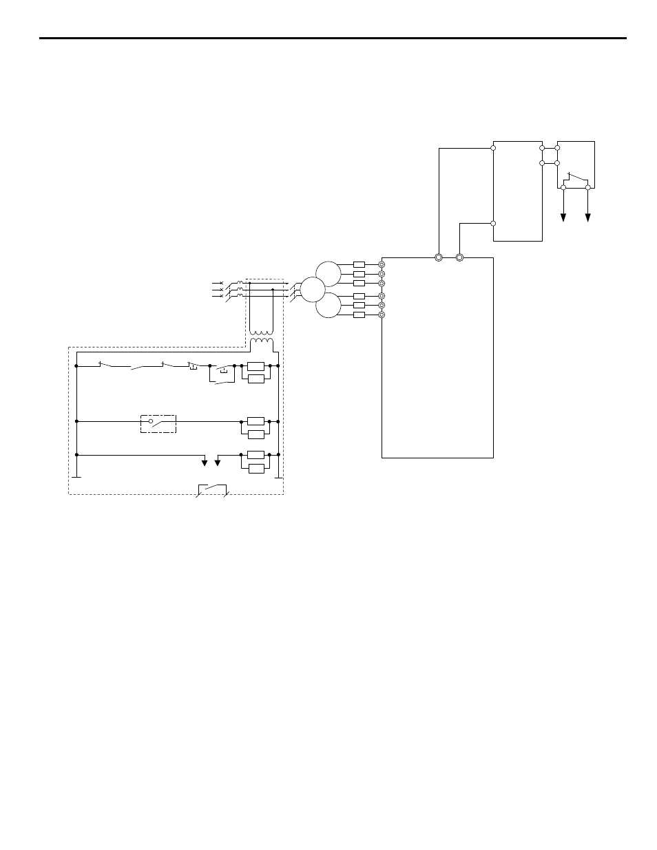
Dynamic Braking Resistor Overload Protection
When using a dynamic braking resistor option, interrupt the power supply using a sequence such as the one shown in
for protection in the event of braking resistor overheat.
Drive
400 V
MC
R
S
T
CDBR dynamic
braking unit
<1>
Dynamic
braking
resistor
<2>
1
2
+3
-
MC
2MCCB
MB
ON
OFF
THRX
SA
1
2
TRX
MC MA
TRX
Fault Relay
Contact
Braking Resistor Unit
Thermal Relay Trip Contact
MC
MC
SA
SA
THRX
R/L1
S/L2
T/L3
R1/L11
S1/L21
T1/L31
Y
Δ
Δ
Figure 18 Power Supply Interrupt for Dynamic Braking Resistor Overheat Protection
<1> A CDBR dynamic braking unit cannot be connected to models 4T0058o or 4T0072o.
<2> A dynamic braking resistor can be connected to the B1 and B2 terminals on models 4T0058o and 4T0072o.
Installing a CDBR Dynamic Braking Unit
Connect the
⊕3 terminal from the drive to the positive terminal on the CDBR dynamic braking unit and wire together the
negative terminals on the drive and CDBR dynamic braking unit.
Connect the dynamic braking resistor to CDBR dynamic braking unit terminals
⊕0 and ⊖0. Refer to
Wire the thermal overload relay normally open contacts of the CDBR dynamic braking unit and the dynamic braking resistor
in parallel, and connect this signal to a control circuit as shown in
to interrupt the main input power supply to the
drive in the event of an overload.
Set L8-55 to 0 to disable dynamic braking transistor protection.
6 Drive Options and Peripheral Devices
YASKAWA TOEP YAIA1U 02A YASKAWA AC Drive – A1000 6-Phase/12-Pulse Input Installation Manual
33