Wiring grounding, Figure 1-2. correct ground connection – Yaskawa V7N Drive with DeviceNet User Manual
Page 10
Section 4
•
•
•
•
•
•
•
•
•
•
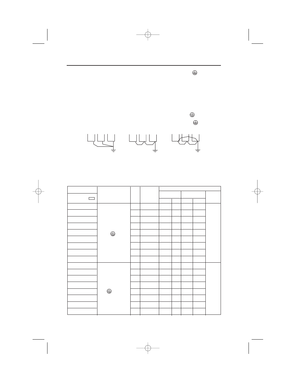
CORRECT
CORRECT
NOT
ACCEPTABLE
• The Drive must be solidly grounded using the main circuit ground terminal .
• If Drive is installed in a cabinet with other equipment, ground leads for all equipment
should be connected to a common low-impedance ground point within the cabinet.
• The supply neutral should be connected to the ground point within the cabinet.
• Select appropriate ground wire size from Table 1-1.
• Make all ground wires as short as practical.
• NEVER ground the Drive in common with welding machines, or other high power electrical
equipment.
• Where several Drives are used, ground each directly to the ground point (see Figure 1-2).
DO NOT FORM A LOOP WITH THE GROUND LEADS.
• When connecting a motor to the Drive’s output terminals, include a separate ground wire.
Attach ground wire solidly to motor frame and to Drive’s ground terminal .
• When using armored or shielded cable for connection between Drive and motor, solidly
connect armor or shield to motor frame, and to the Drive’s ground terminal .
Figure 1-2. Correct Ground Connection
Model
Tightening
Wire
Terminal Symbol
Screw
Torque
Applicable
Recommended
CIMR-V7NU
lb • in
size
size Type
(N • m)
mm
2
AWG
mm
2
AWG
20P1
M3.5
7.1 to 8.88
0.75 to 2 18 to
2
14
(0.8 to 1.0)
14
20P2
M3.5
7.1 to 8.88
0.75 to 2 18 to
2
14
(0.8 to 1.0)
14
20P4
L1(R), L2(S), L3(T)
M3.5
7.1 to 8.88
0.75 to 2 18 to
2
14
B1, B2
(0.8 to 1.0)
10
20P7
T1(U), T2(V), T3(W)
M3.5
7.1 to 8.88
0.75 to 2 18 to
2
14
-, +1,+2
(0.8 to 1.0)
14
600V
21P5
M4
10.65 to 13.31 2 to 5.5 14 to
2
14
vinyl-
(1.2 to 1.5)
10
sheathed
22P2
M4
10.65 to 13.31 2 to 5.5 14 to
3.5
12
wire or
(1.2 to 1.5)
10
equivalent
23P7
M4
10.65 to 13.31 2 to 5.5 14 to
5.5
10
(1.2 to 1.5)
10
25P5
M5
22.19
5.5 to 8 10 to 8
8
8
(2.5)
27P5
M5
22.19
5.5 to 8 10 to 8
8
8
(2.5)
40P2
M4
10.65 to 13.31 2 to 5.5 14 to
2
14
(1.2 to 1.5)
10
40P4
M4
10.65 to 13.31 2 to 5.5 14 to
2
14
(1.2 to 1.5)
10
40P7
L1(R), L2(S), L3(T)
M4
10.65 to 13.31 2 to 5.5 14 to
2
14
600V
B1, B2
(1.2 to 1.5)
10
vinyl-
41P5
T1(U), T2(V), T3(W)
M4
10.65 to 13.31 2 to 5.5 14 to
2
14
sheathed
-, +1,+2
(1.2 to 1.5)
10
wire or
42P2
x 1
M4
10.65 to 13.31 2 to 5.5 14 to
2
14
equivalent
(1.2 to 1.5)
10
43P7
M4
10.65 to 13.31 2 to 5.5 14 to
2
14
(1.2 to 1.5)
10
3.5 x 1
12 x 1
45P5
M4
12.43
3.5 to 5.5 12 to
5.5
10
(1.4)
10
47P5
M5
22.19
5.5 to 8
12 to
5.5
10
(2.5)
10
Note: The wire size is set for copper wires at 160°F (75°C)
10
Table 1-1. Wire and Terminal Screw Sizes
Wiring
Grounding
IG.V7N.qxd:IG.V7N.qxd 6/5/07 3:22 AM Page 10