Caution, N003 – Yaskawa V7N Drive with DeviceNet User Manual
Page 24
L1 ( R )
L2 ( S )
L3 ( T )
P1
PC
B2
B1
–
+2
+1
AC
MOTOR
T1 ( U )
T2 ( V )
T3 ( W )
MCCB
L1
L2
L3
S1
FORWARD
RUN/STOP
LOGIC
COMMON
TERMINAL
MULTI-FUNCTION
PHOTOCOUPLER
OUTPUT
48V, 50mA OR LESS
3-PHASE
POWER SUPPLY
(Use L1 (R) and
(Note that drive must
be derated by 50%
on 3-Phase Models)
L2 (S) for
single-phase
input)
MULTI-FUNCTION
DEVICENET OUTPUT
MULTI-FUNCTION
DEVICENET INPUT
SHIELD
CONNECTION
REVERSE
RUN/STOP
S2
S4
S3
S5
S6
FAULT
RESET
EXTERNAL
FAULT
MULTI-STEP
SPEED REF 1
S7
SC
V7N
MULTI-FUNCTION
CONTACT INPUT
MA
MC
RUNNING
FAULT
FOR DYNAMIC BRAKING
(See Note 4)
FOR DC REACTOR
(See Note 5)
(See Note 5)
*
P2
SPEED
COINCIDENCE
(See Note 6)
(See Note 3)
(See Note 1)
1OL (See Note 2)
*
*
*
1OL
(See
Note 3)
MULTI-STEP
SPEED REF 2
JOG REFERENCE
FIG. 1-9
FREQUENCY
SETTING
POT
MIN
SW1
BAUD RATE
PNP
NPN
MAX
V
0 ~ 10V
4 ~ 20 mA
Common
CN2
I
C
MULTI-FUNCTION
ANALOG INPUT
BLACK
BLUE
GREEN
WHITE
RED
V-
CAN_L
SHIELD
CAN_H
V+
(See Note 7)
(See Note 7)
1-3 FU
*
(See Note 8)
DEVICENET
TERMINALS
0
5
3
4
2
7
8
1
6
9
0
5
3
4
2
7
8
1
6
9
0
5
3
4
2
7
8
1
6
9
MSD LSD
ADDRESS
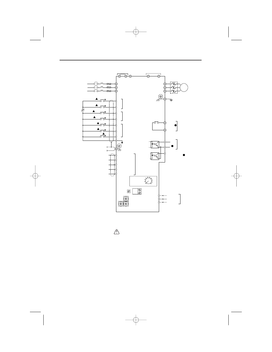
Figure 1-5. Standard Connections (2-Wire Control)
(Parameter n001 set to “10”)
•
After wiring is complete, verify that all wiring is correctly installed, excess
screws and wire clippings are removed from inside of unit, screws are securely
tightened, and exposed wire does not contact other wiring or terminals.
•
The Drive leaves the factory with all parameters set for 2-wire external control/
reference control. To use the Drive in a 3-wire application, Drive parameters n001,
n003 and n004 must be reprogrammed and Figure 1-6 used for all external
connections.
•
If a FWD or REV run command is given from the control circuit terminal when the
operation method selection function (
n003
) is set to “ 1 ” and the “LO/RE”
selection is set to “RE”, the motor will start automatically as soon as power is
applied to the main circuit.
CAUTION
24
Section 8
Interconnection Diagram
2-Wire Control
IG.V7N.qxd:IG.V7N.qxd 6/5/07 3:22 AM Page 24