Caution – Yaskawa V7N Drive with DeviceNet User Manual
Page 20
20
Section 6
Peripheral
Devices
The following peripheral devices may be required to be mounted between the AC main circuit power
supply and the Drive input terminals L1 (R), L2 (S) and L3 (T).
Never connect a general LC/RC noise filter to the Drive output circuit.
Never connect a phase-advancing capacitor to the input/output sides or a
surge suppressor to the output side of the Drive.
When a magnetic contactor is installed between the Drive and the motor,
never turn it on or off during operation.
Note: For more details on peripheral devices, contact your manufacturer.
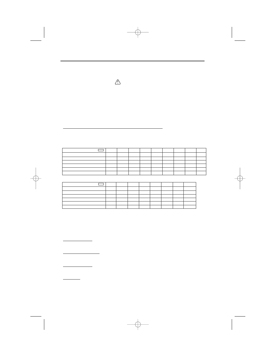
Recommended Branch Short Circuit Protection Peripheral Devices
All models have UL evaluated motor overload protection built in. Motor overload protection
is also provided in accordance with the NEC and CEC. Additional branch circuit overload
protection is not required.
230V 3-Phase
460V 3-Phase
Notes:
(1)
Apply UL designated Class RK5 fuses.
(2)
Apply UL designated Class CC or T non-time delay fuses.
Input fuse sizes are determined by NEC guidelines, and should not exceed the ratings shown in the table.
Fuse Ratings are based upon 250V fuses for 230V Drives, and 600V for 460V Drives
Fuse Manufacturer’s Designators:
Class CC: KTK, FNQ or equivalent
Class RK5: FRN, FRS or equivalent
Class T: JJS, JJN or equivalent
Magnetic Contactor
Mount a surge protector on the coil. When using a magnetic contactor to start and stop the Drive, do
not exceed one start per hour.
Ground Fault Interrupter
Select a ground fault interrupter not affected by high frequencies. To prevent malfunctions, the
current should be 200mA or more and the operating time 0.1 second or more.
AC and DC Reactor
Install a reactor to connect to a power supply transformer of large capacity (600 kVA or more) or to
improve the power factor on the power supply side.
Noise Filter
Use a noise filter exclusively for the Drive if radio noise generated from the Drive causes other
control devices to malfunction.
Model
CIMR-V7NU
20P1
20P2
20P4
20P7
21P5
22P2
23P7
25P5
27P5
Capacity (kVA)
0.3
0.6
1.1
1.9
3.0
4.2
6.7
9.5
13.0
Rated output current (A)
0.8
1.6
3.0
5.0
8.0
11.0
17.5
25.0
33.0
Rated input current (A)
1.1
1.8
3.9
6.4
11.0
15.1
24.0
33.0
39.6
Max. Time Delay Fuse Rating (A)
(1)
1.8
3.2
6.25
10.0
17.5
20.0
25.0
45.0
60.0
Max. Non-Time Delay Fuse Rating (A)
(2)
3.0
5.0
10.0
20.0
30.0
45.0
45.0
70.0
80.0
Max. MCCB Rating (A)
15.0
15.0
15.0
15.0
20.0
30.0
40.0
50.0
60.0
Model
CIMR-V7NU
40P2
40P4
40P7
41P5
42P2
43P7
45P5
47P5
Capacity (kVA)
0.9
1.4
2.6
3.7
4.2
7.0
11.0
14.0
Rated output current (A)
1.2
1.8
3.4
4.8
5.5
9.2
14.8
18
Rated input current (A)
1.6
2.4
4.7
7.0
8.1
12.0
19.6
23.8
Max. Time Delay Fuse Rating (A)
(1)
2.8
4.0
8.0
12.0
12.0
20.0
35.0
45.0
Max. Non-Time Delay Fuse Rating (A)
(2)
5.0
7.0
12.0
20.0
20.0
35.0
60.0
70.0
Max. MCCB Rating (A)
15.0
15.0
15.0
15.0
15.0
20.0
30.0
40.0
CAUTION
IG.V7N.qxd:IG.V7N.qxd 6/5/07 3:22 AM Page 20