Yaskawa V7N Drive with DeviceNet User Manual
Page 9
9
Main Circuit Input /Output Wiring
• Use 600V vinyl-sheathed wire or equivalent. Wire size and type should be determined by local
electrical codes.
• Avoid routing power wiring near equipment sensitive to electrical noise.
• Avoid running input and output wiring in the same conduit.
• NEVER connect AC main power to output terminals T1(U), T2(V), and T3(W).
• NEVER allow wire leads to contact metal surfaces. Short-circuit may result.
• NEVER connect power factor correction capacitors to the Drive output. Consult Yaskawa when
connecting noise filters to the Drive output.
• WIRE SIZING MUST BE SUITABLE FOR CLASS I CIRCUITS.
• When connecting motor to Drive’s output terminals, include a separate ground wire. Attach ground
wire solidly to motor frame and to Drive’s ground terminal .
• When using armored or shielded cable for connection between Drive and motor, solidly connect
armor or shield to motor frame, and to Drive’s ground terminal .
• Motor lead length should NOT EXCEED 164 feet (50 meters), and motor wiring should be run in a
separate conduit from the power wiring. If lead length must exceed this distance, reduce carrier
frequency (see TM.V7N.01, paragraph 5.8) and consult factory for proper installation procedures.
• Use UL listed closed loop connectors or CSA certified ring connectors sized for the selected wire
gauge. Install connectors using the correct crimp tool recommended by the connector manufacturer.
Control Circuit
• Interconnections for external two-wire control in combination with the Digital Operator are shown in
Figure 1-5.
• Interconnections for external three-wire control in combination with the Digital Operator are shown
in Figure 1-6.
Note: Make wire connections according to Figure 1-5 and Table 1-2; observe the following:
• Signal Leads: Terminals S1-S4 & SC.
• Control Leads: Terminals P1, P2 & PC.
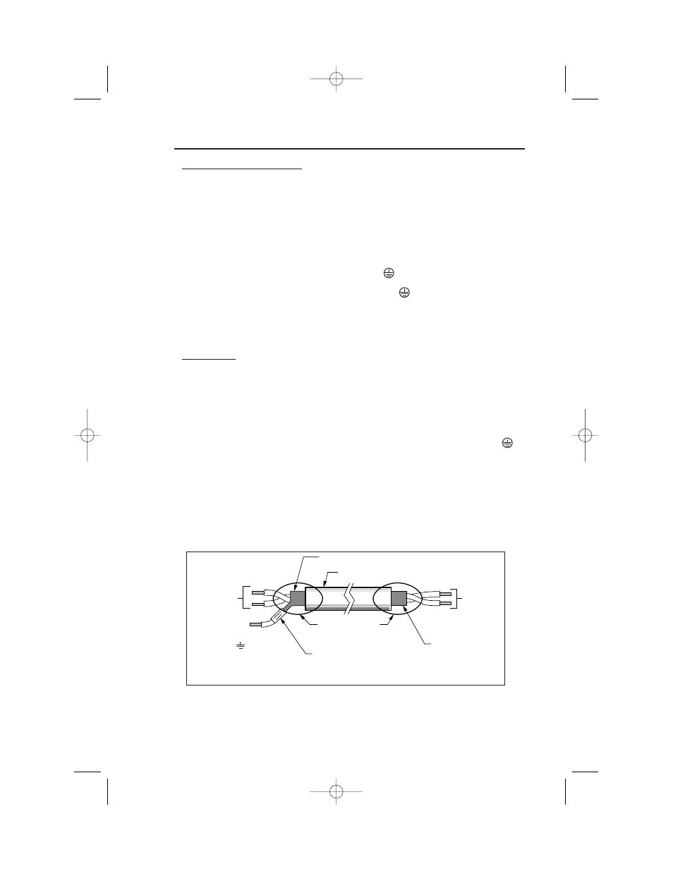
• Use twisted shielded or twisted-pair shielded wire (20-16 AWG [0.5 – 1.25mm2]) for control and
signal circuit leads. The shield sheath MUST be connected at the Drive end ONLY (terminal ).
The other end should be dressed neatly and left unconnected (floating). See Figure 1-1.
• DeviceNet Leads: Black, Blue, Shield, White, Red.
• Use DeviceNet thick or thin cable specified by ODVA.
• Signal leads and feedback leads (PG) must be separated from control leads main circuit leads, and
any other power cables, to prevent erroneous operation caused by electrical noise.
• Lead length should NOT EXCEED 164 feet (50 meters). Wire sizes should be determined
considering the voltage drop.
• All AC relays, contactors and solenoids should have RC surge supressors installed across their
coils.
• All DC relays, contactors and solenoids should have diodes installed across their coils.
TO DRIVE
SIGNAL
TERMINALS
TO SHIELD
SHEATH
TERMINAL
(TERM. )
WRAP BOTH ENDS
OF SHEATH WITH
INSULATING TAPE
CRIMP
CONNECTION
SHIELD SHEATH
OUTER JACKET
DO NOT
CONNECT
TO
EXTERNAL
CIRCUIT
Figure 1-1. Shielded Sheath Termination
Wiring
Main and Control Circuit
Section 4
IG.V7N.qxd:IG.V7N.qxd 6/5/07 3:22 AM Page 9