5 absolute data reception sequence, 1) outline of absolute data, 46 and 64 – Yaskawa Sigma-5 User Manual: Design and Maintenance - Rotary Motors MECHATROLINK-III Communications Reference User Manual
Page 127: Phase-c output specifications
4 Operation
4.7.5 Absolute Data Reception Sequence
4-42
4.7.5 Absolute Data Reception Sequence
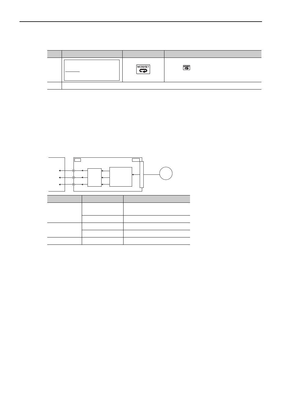
The sequence in which the SERVOPACK receives outputs from the absolute encoder and transmits them to
host controller is shown below.
(1) Outline of Absolute Data
The serial data, pulses, etc., of the absolute encoder that are output from the SERVOPACK are output from the
PAO, PBO, and PCO signals as shown below.
Phase-C Output Specifications
The pulse width of phase C (origin pulse) changes depending on the encoder output pulse (Pn212), becoming
the same width as phase A.
The output timing is one of the following.
• Synchronized with the rising edge of phase A
• Synchronized with the falling edge of phase A
• Synchronized with the rising edge of phase B
• Synchronized with the falling edge of phase B
Note: When host controller receives the data of absolute encoder, do not perform counter reset using the output of PCO
signal.
5
Press the
Key to return to the display of the pro-
cedure 1.
6
To enable the change in the setting, turn the power OFF and ON again.
(cont’d)
Step
Panel Display
Keys
Description
B B
F n 0 0 6 : A l m H i s t C l r
F n 0 0 8 : M t u r n C l r
F n 0 0 9 : R e f A d j
F n 0 0 A : V e l A d j
- F U N C T I O N -
Signal Name
Status
Contents
PAO
At initialization
Rotational serial data
Initial incremental pulses
Normal Operations
Incremental pulses
PBO
At initialization
Initial incremental pulses
Normal Operations
Incremental pulses
PCO
Always
Origin pulses
ENC
CN1
PAO
PBO
PCO
CN2
Serial
data
Serial data→
pulse conversion
Host
controller
SERVOPACK
Dividing
circuit
(Pn212)
46 and 64