Yaskawa Sigma-5 User Manual: Design and Maintenance - Rotary Motors MECHATROLINK-III Communications Reference User Manual
Page 347
10 Appendix
10.1.2 Parameters
10-16
Pn424
2
Torque Limit at Main Circuit
Voltage Drop
0 to 100
1%
50
Immediately
Setup
−
4.3.7
Pn425
2
Release Time for Torque
Limit at Main Circuit Voltage
Drop
0 to 1000
1 ms
100
Immediately
Setup
−
Pn456
2
Sweep Torque Reference
Amplitude
1 to 800
1%
15
Immediately
Tuning
−
6.21
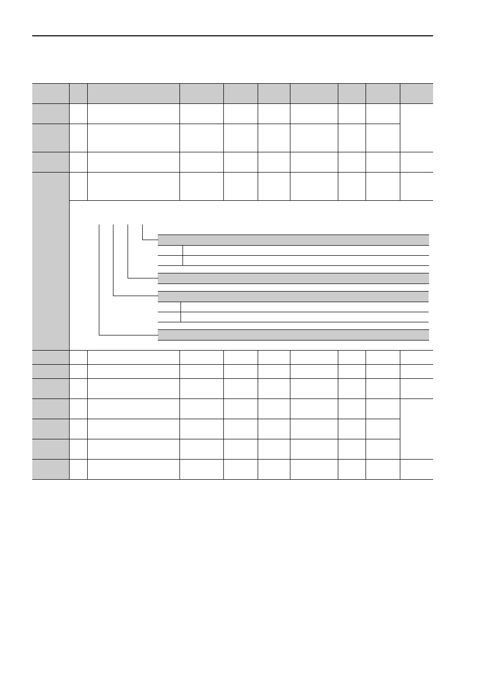
Pn460
2
Notch Filter Adjustment
Switch
0000 to 0101
−
0101
Immediately
Tuning
−
5.2.1
5.3.1
5.5.1
Pn501
2
Zero Clamp Level
0 to 10000
1 min
-1
10
Immediately
Setup
−
−
Pn502
2
Rotation Detection Level
1 to 10000
1 min
-1
20
Immediately
Setup
−
4.8.3
Pn503
2
Speed Coincidence Signal
Output Width
0 to 100
1 min
-1
10
Immediately
Setup
−
4.8.5
Pn506
2
Brake Reference - Servo OFF
Delay Time
0 to 50
10 ms
0
Immediately
Setup
−
4.3.4
Pn507
2
Brake Reference Output
Speed Level
0 to 10000
1 min
-1
100
Immediately
Setup
−
Pn508
2
Waiting Time for Brake
Signal When Motor Running
10 to 100
10 ms
50
Immediately
Setup
−
Pn509
2
Instantaneous Power Cut
Hold time
20 to 1000
1 ms
20
Immediately
Setup
−
4.3.6
(cont’d)
Parameter
No.
Size
Name
Setting
Range
Units
Factory
Setting
When
Enabled
Classi-
fication
Profile
Reference
Section
Notch Filter Adjustment Selection 1
0
Does not adjust 1st step notch filter automatically using utility function.
1
Adjust 1st step notch filter automatically using utility function.
Reserved (Do not change.)
Notch Filter Adjustment Selection 2
0
Does not adjust 2nd step notch filter automatically using utility function.
1
Adjust 2nd step notch filter automatically using utility function.
Reserved (Do not change.)
4th 3rd 2nd 1st
digit digit digit digit
n.