Bus / ring configuration – Rose Electronics UltraMatrix Remote 2 User Manual
Page 15
ULTRAMATRIX REMOTE 2 INSTALLATION AND OPERATIONS MANUAL
9
Pre-Configuration procedure
a. Call up the Configuration menu system by pressing and releasing the left [Ctrl] key, then the [F12] key.
b. Select “Computer” and press [Enter]
c. Select the computer to change the default keyboard and/or mouse type, and then select the keyboard or
mouse field for the selected computer and press [Enter]. A selection box will display, listing the supported
keyboard or mouse types.
d. Select the correct keyboard or mouse type for the selected computer and press [Enter].
e. Press [ESC] to return to the “Main menu” and save the changes.
f. Connect the computer to the pre-configured CPU port.
5. Boot the computer the KVM station is connected to if the computer power was off. You should see the boot up
sequence on the KVM monitor. If the computer was connected to a pre-configured CPU port with power applied,
you should see that computers video.
6. Verify that the keyboard, video, and mouse on the connected computer function properly before proceeding. Verify
that other KVM stations operate properly.
Switch KVM station #1 to the next sequential CPU port as explained in step 3 and perform steps 4-6 for that
computer and for the remaining computers.
Bus / Ring Configuration
If your system demands are greater than a single model can provide, you can expand the UltraMatrix Remote 2 to
other UltraMatrix “E” series models. The expansion units should have the same number of CPU ports as the main
UltraMatrix Remote 2 unit has. If the main unit has 8 CPU ports, the expansion units should also have 8 CPU ports.
The total number of expansion units that can be added is equal to 1000 divided by the number of CPU ports on the
main unit. If the UltraMatrix Remote 2 unit has 8 CPU ports, then the total number of expansion units is 1000 divided
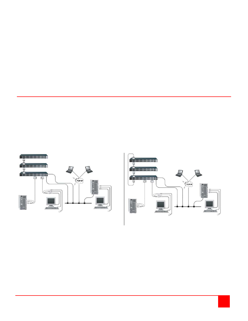
by 8, or 125 additional expansion units. A 16 CPU port model can have 62 expansion units. Figure 5 show a typical
bus expansion configuration using an UltraMatrix Remote 2, 8 port master and two UltraMatrix “E” series, 8 port units
as expansion units. Figure 6 shows a typical Ring configuration
If you plan to expand your system, the unit designated as the “Main Unit” must be configured to identify that there is an
expanded system. This is explained in appendix L for a Bus configuration and appendix M for a ring configuration.
Figure 5. Bus Configuration
Figure 6. Ring Configuration
NOTE: The IP input module(s) must be configured prior to configuring an expanded system